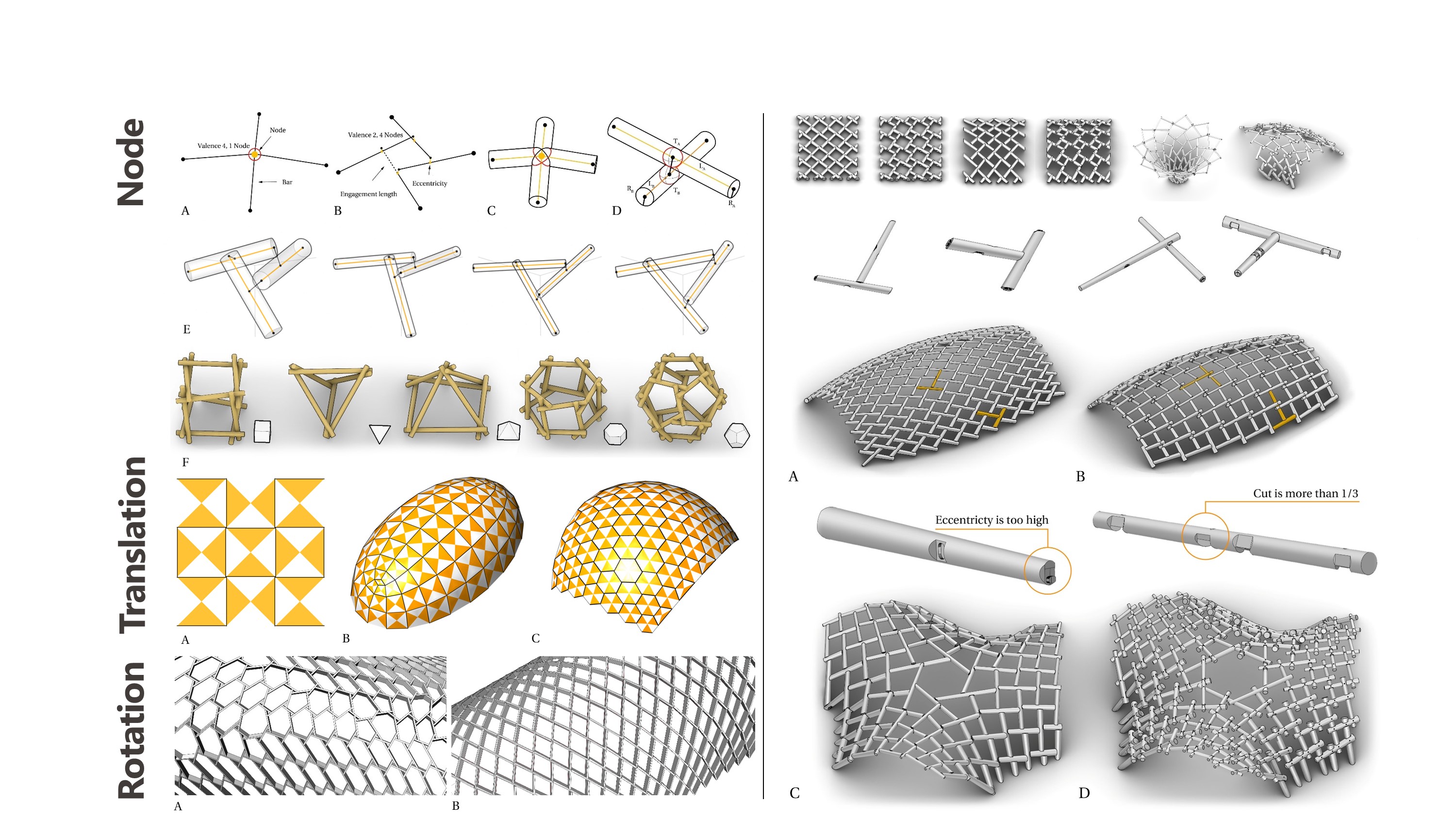
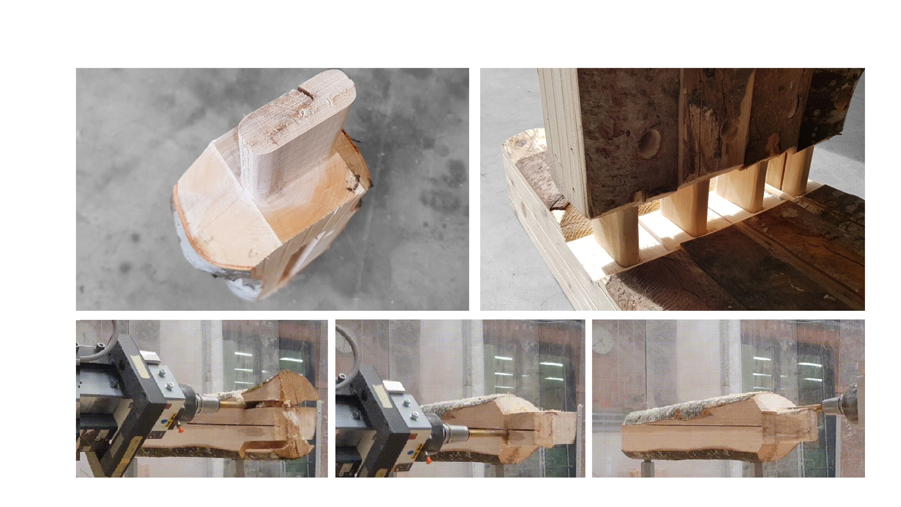
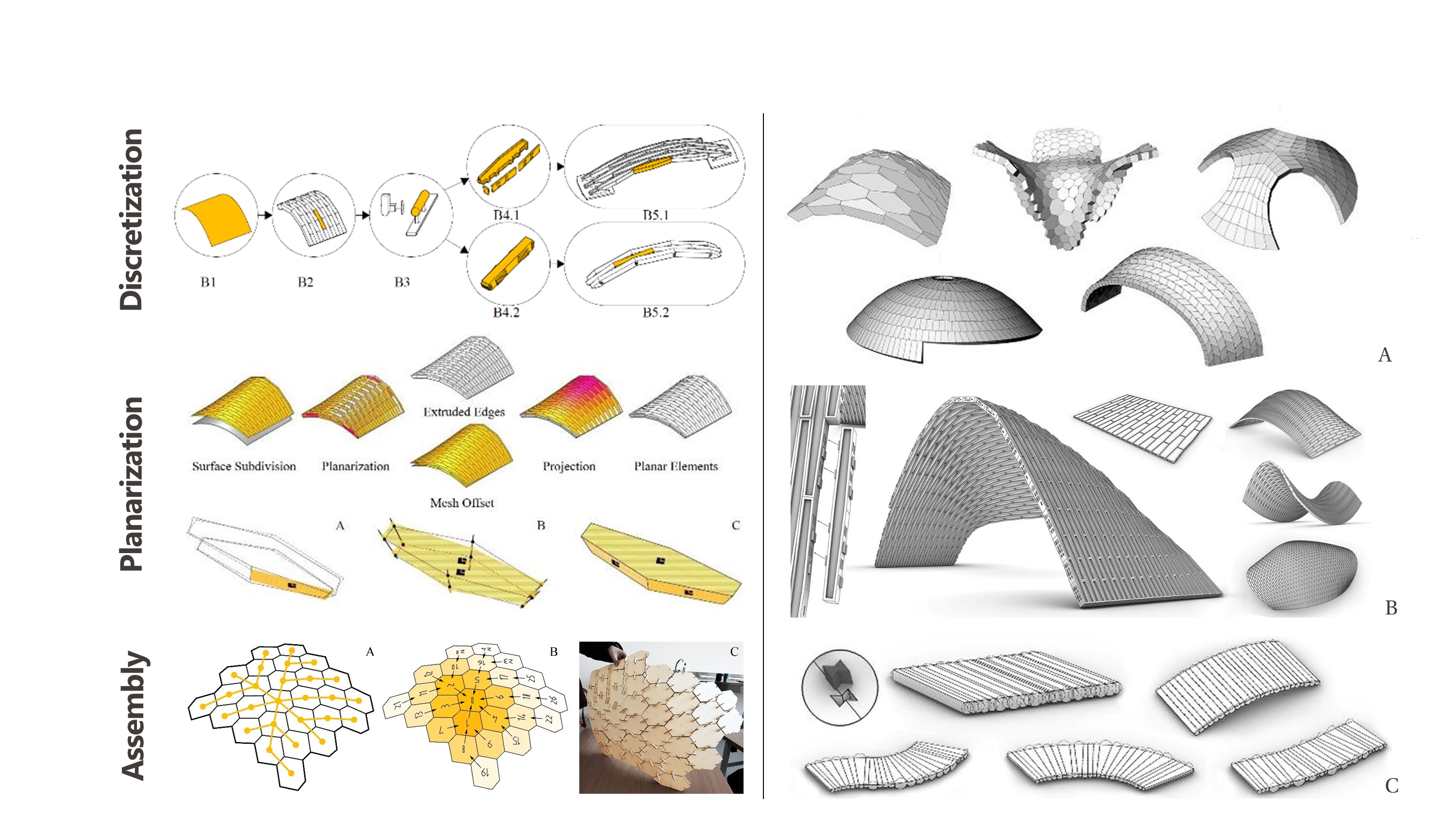
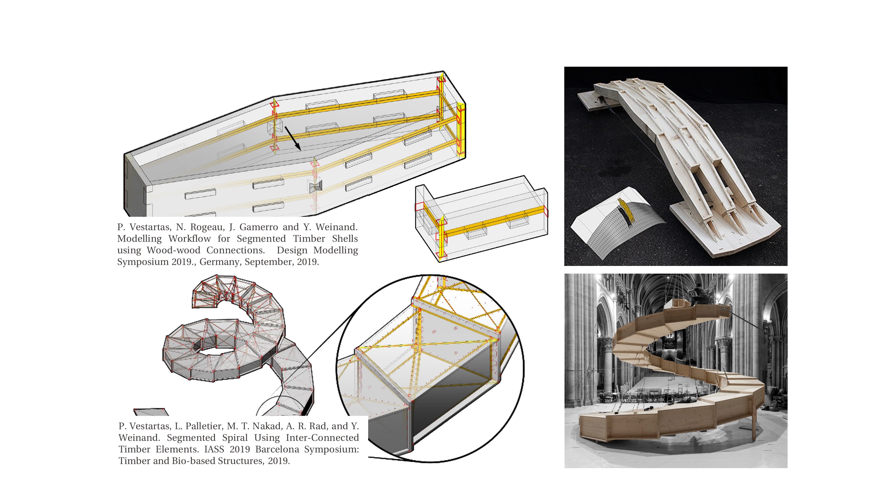
General Description
Scope - Pair-wise Connections
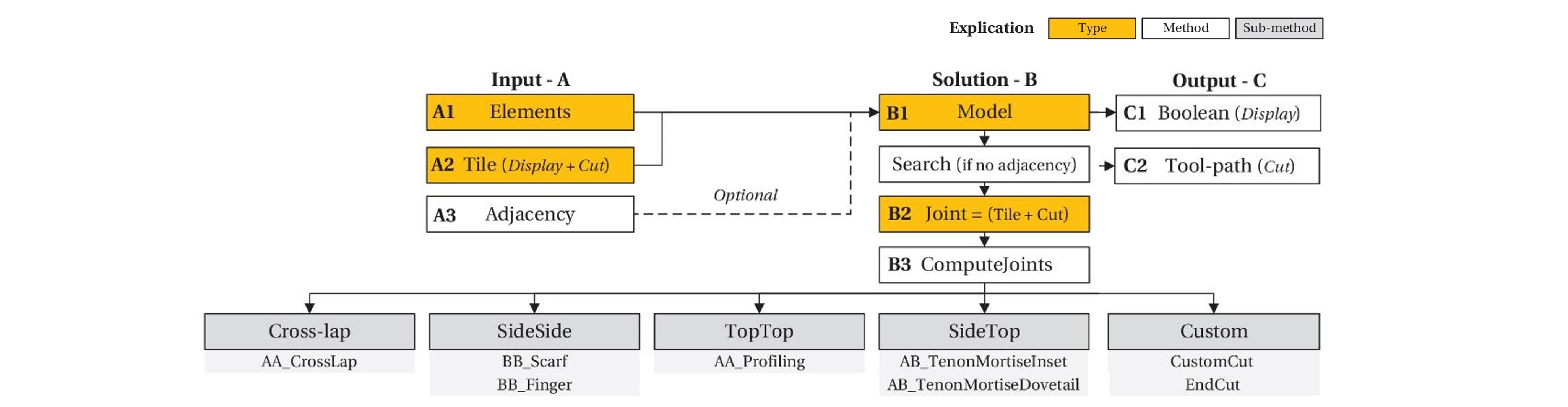
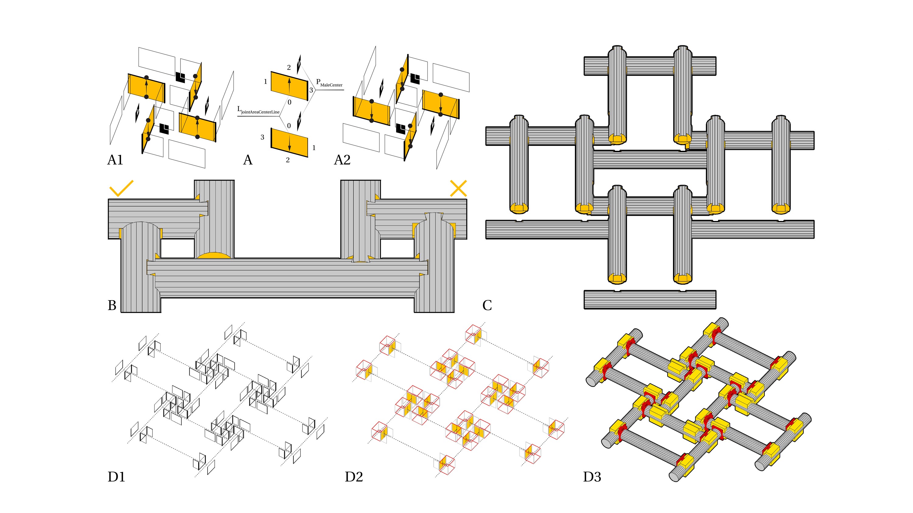
Algorithm Structure
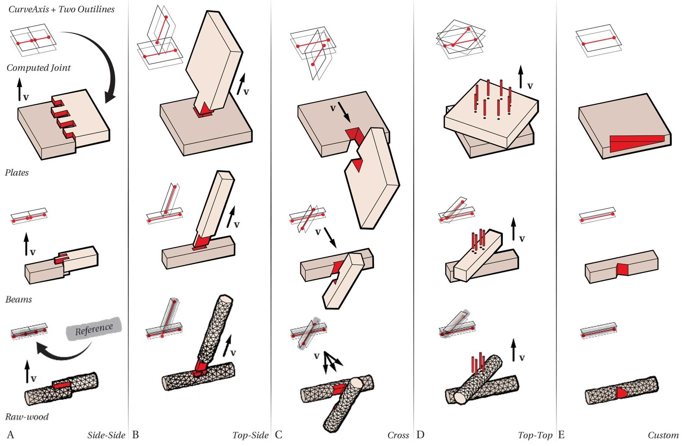
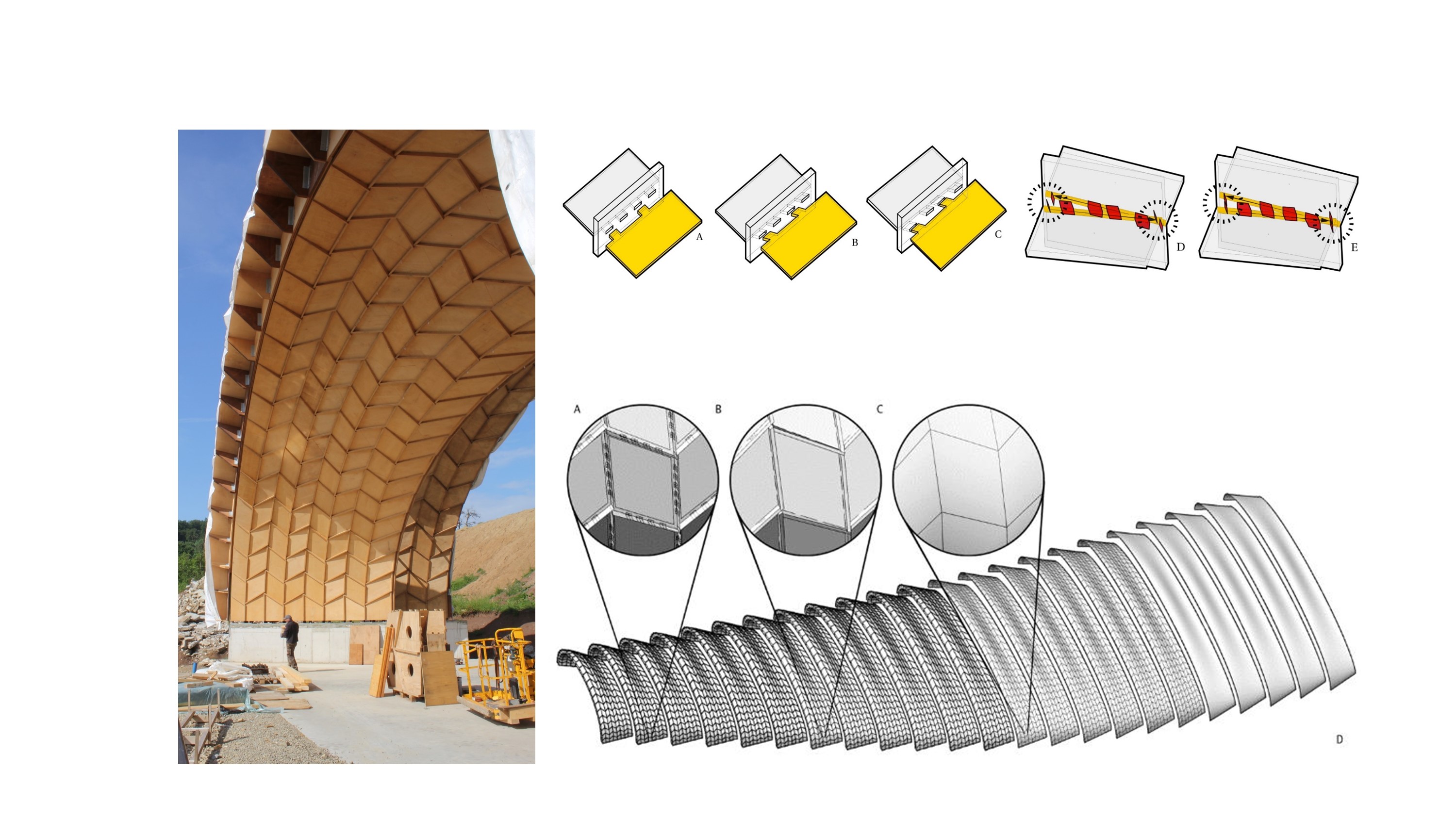
Joint Types
- Joint parameters are given in a list following this order:
side-to-side parallel in-plane | side-to-side parallel | side-to-side out-of-plane | top-to-side | cross | top-to-top | side-to-side non-parallel
- division length | shift | type |
{ 1000, 0.5, 1, 1000, 0.5, 10 , 1000, 0.5, 20 , 1000, 0.5, 30 , 1000, 0.5, 40 , 1000, 0.5, 50 }
- Code implementation:
- how to a custom construct joint
string, name of a joint e.g. “ss_e_ip_0”
std::vector<CGAL_Polyline> m[2] - 2 plines lists, where 1st list are bottom and 2nd are top plines
std::vector<CGAL_Polyline> f[2] - 2 plines lists, where 1st list are bottom and 2nd are top plines
std::vector<char> - list of boolean types for the “m” array, length matches m list length
std::vector<char> - list of boolean types for the “f” array, length matches f list length
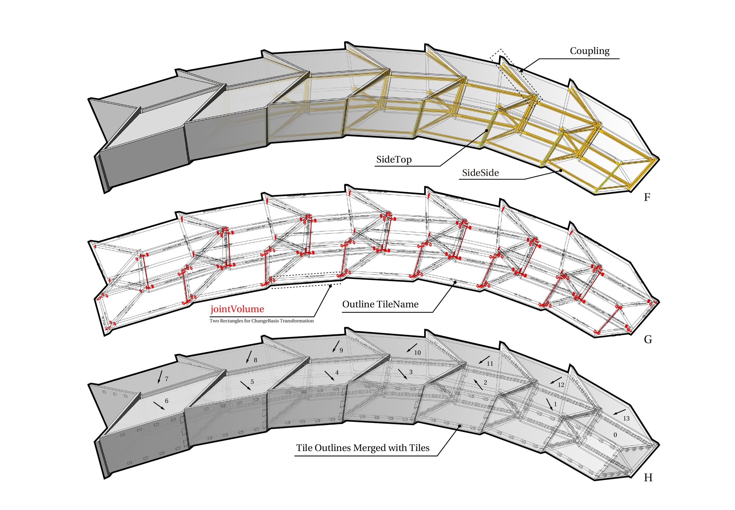
joint class that stores adjacency information
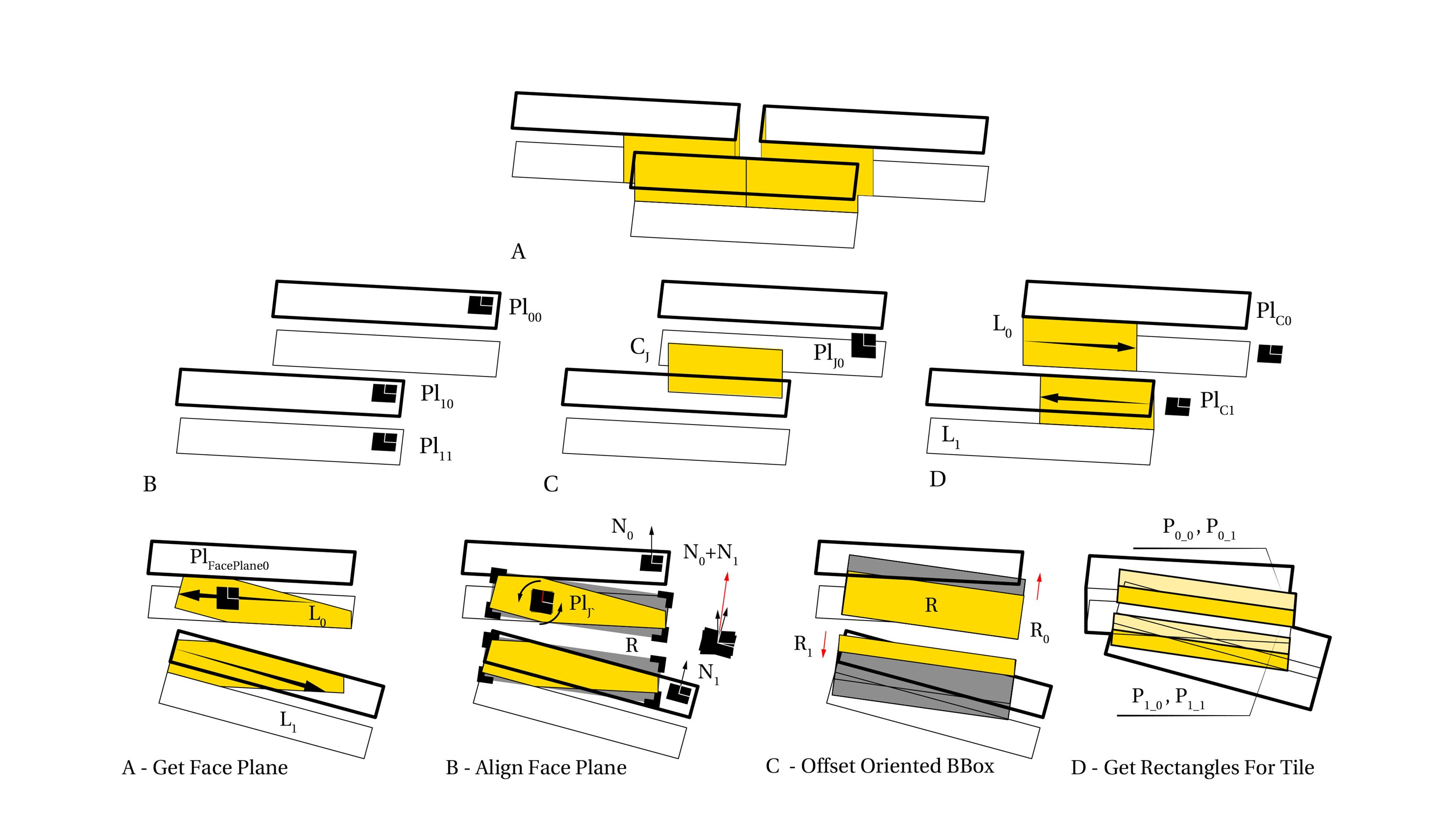
change-basis transformation from unit tile to joint volume defined by two rectangles
assignment of joints based and search categories and connection types
store each parameterized joint inside std::unordered_map<string, joint> that is not remapped yet
Joints in the Joint Library:
Types_0 |
Types_1-9 |
Types_10-19 |
Types_20-29 |
Types_30-39 |
Types_40-49 |
Types_50-59 |
|---|---|---|---|---|---|---|
skip |
side-to-side |
side-to-side |
top-to-side |
cross |
top-to-top |
side-to-side |
in-plane |
out-of-plane |
rotated |
||||
default ss_e_ip_1 |
default ss_e_op_1 |
default ts_e_p_3 |
default cr_c_ip_0 |
default |
default |
|
1 - (ss_e_ip_1) |
10 - (ss_e_op_1) |
20 - (ts_e_p_1) |
30 - (cr_c_ip_0) |
|||
2 - (ss_e_ip_0) |
11 - (ss_e_op_2) |
21 - (ts_e_p_2) |
31 - (cr_c_ip_1) |
|||
12 - (ss_e_op_0) |
22 - (ts_e_p_3) |
|||||
23 - (ts_e_p_0) |
||||||
custom 9 ss_e_ip_9 |
custom 19 ss_e_op_9 |
custom 29 ts_e_p_9 |
custom 39 cr_c_ip_9 |
custom 49 tt_e_p_9 |
custom 59 ss_e_r_9 |
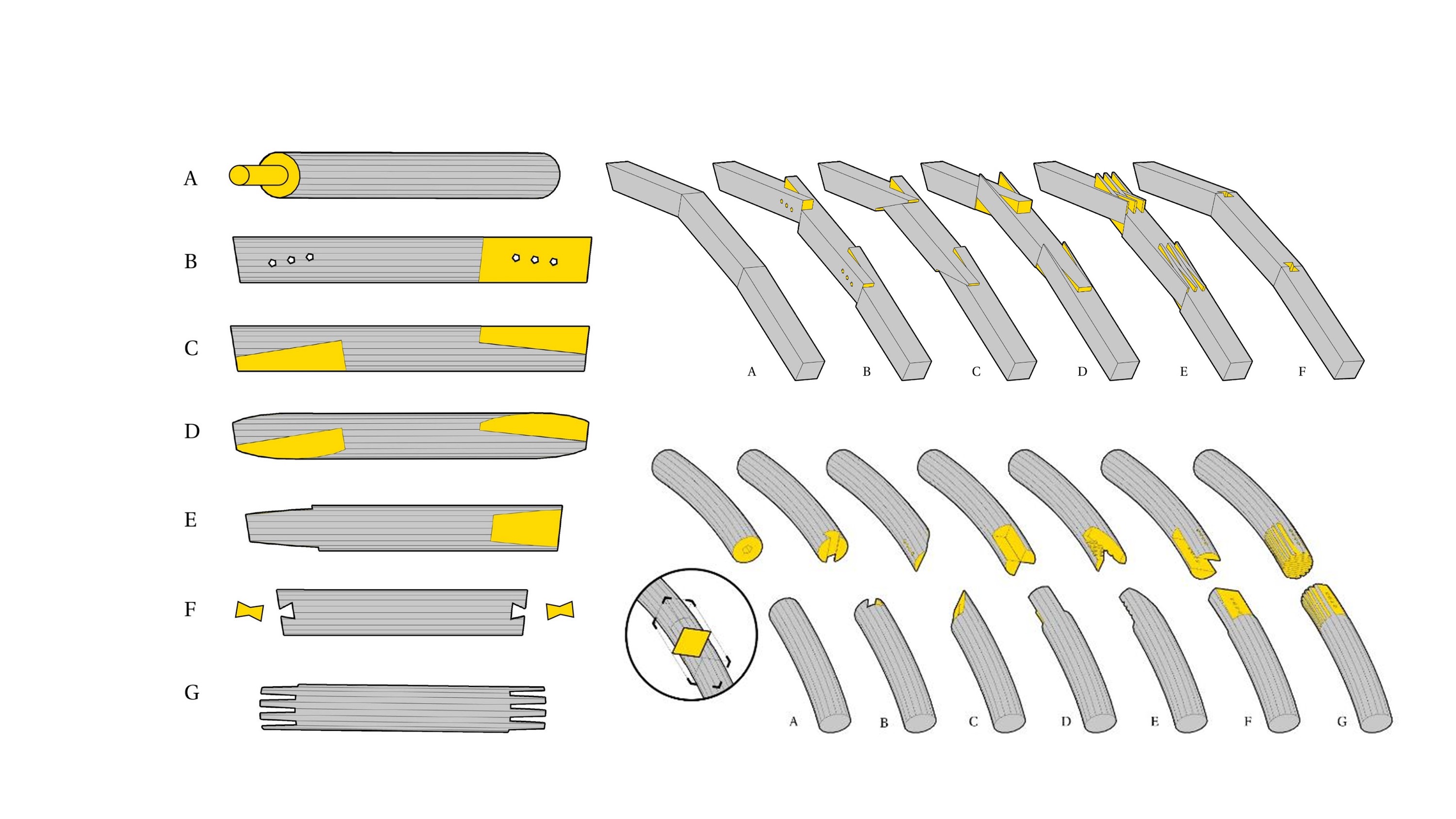
- Joints have two properties m_boolean_type and f_boolean_type to guide the fabrication process:
Default nothing = ‘0’
Plates edge_insertion = ‘1’
Plates hole = ‘2’,
Plates insert_between_multiple_edges = ‘3’
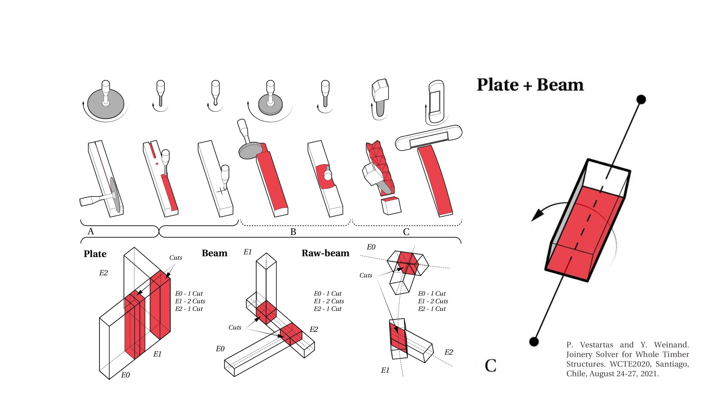
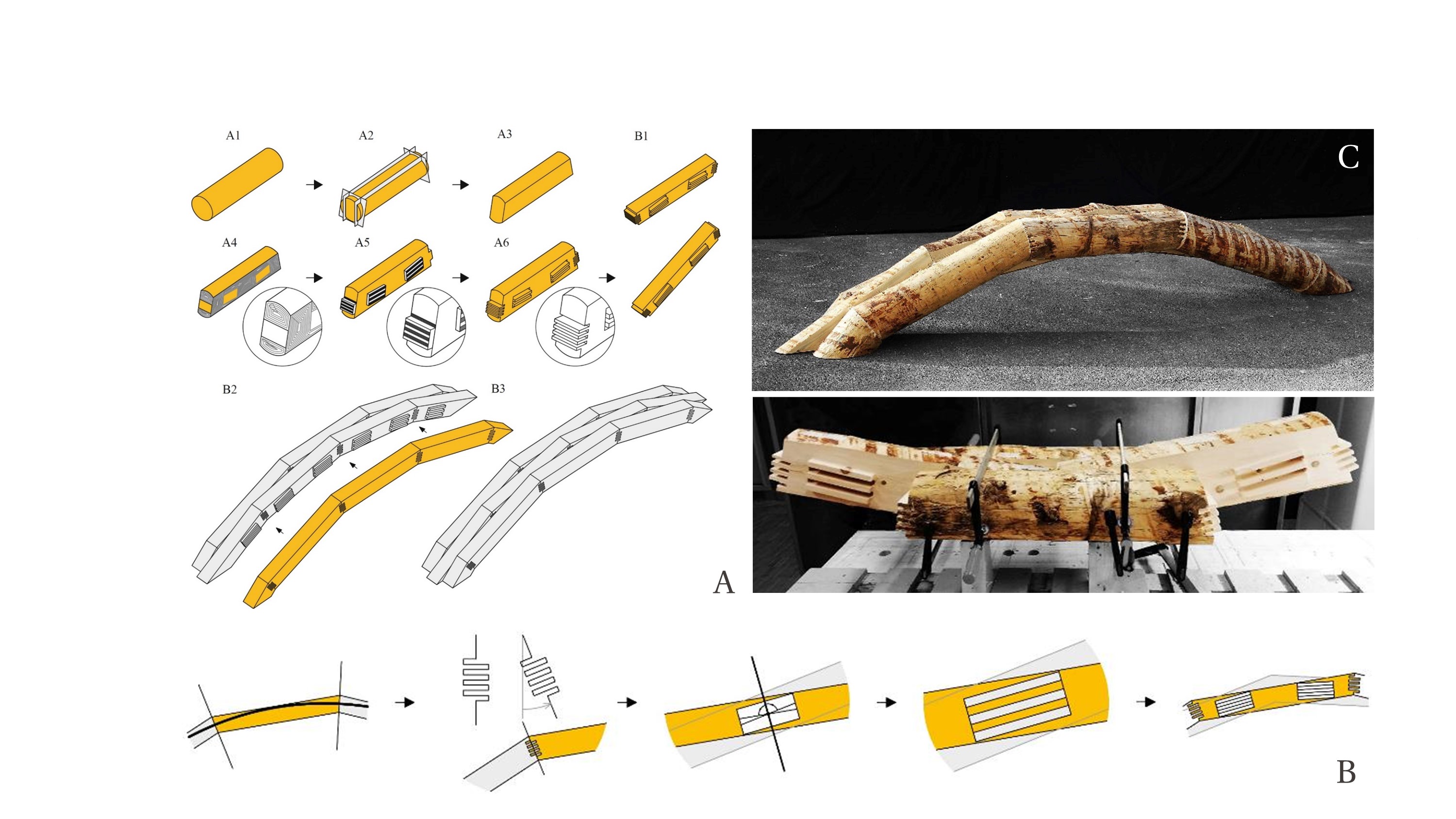
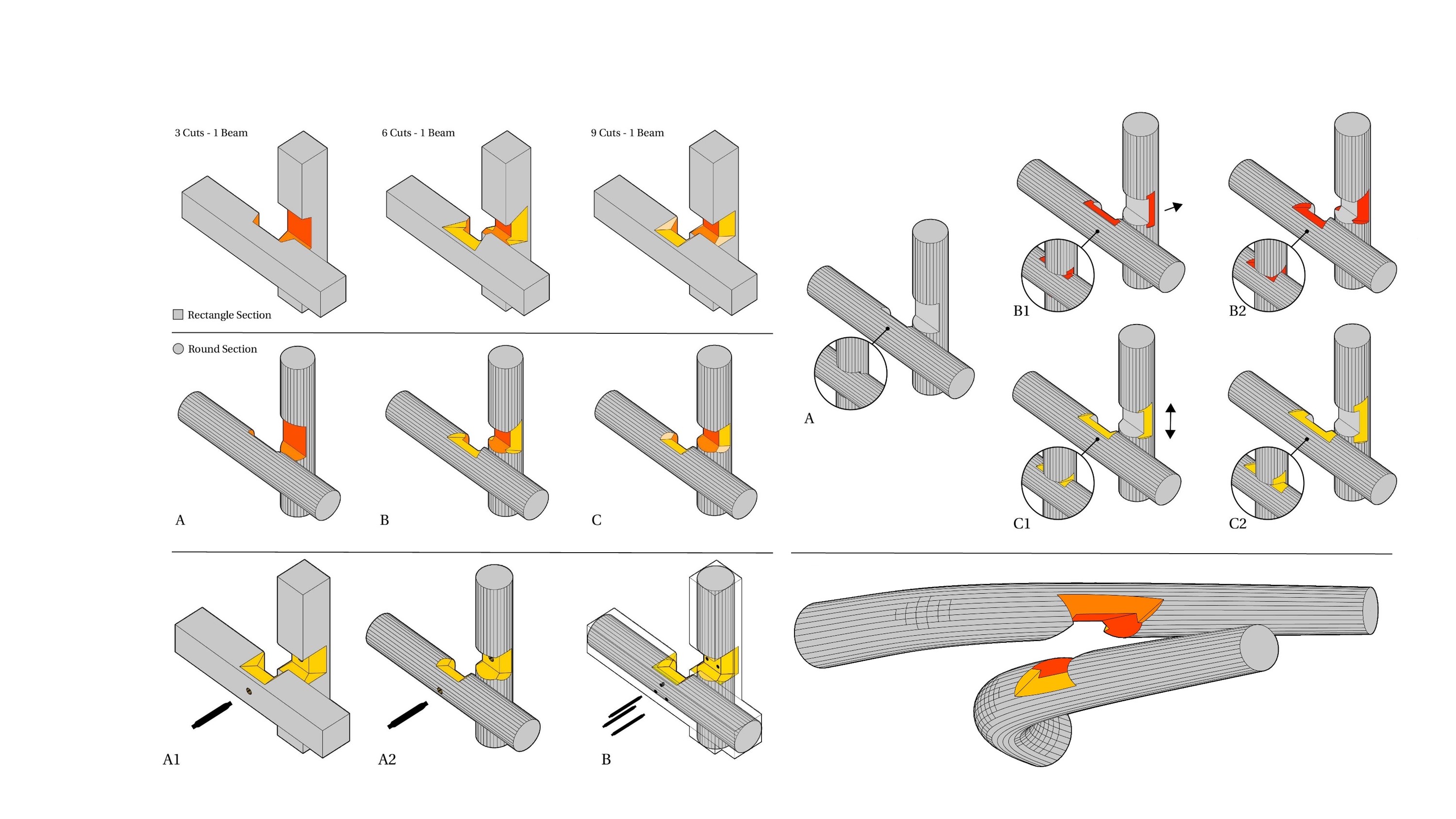
Beams slice = ‘4’ //project and make rectangle
Beams mill = ‘5’,
Beams mill_project = ‘6’ //project
Beams cut = ‘7’
Beams cut_project = ‘8’ //project
Beams binary_slice_mill = ‘9’ //project and make rectangle
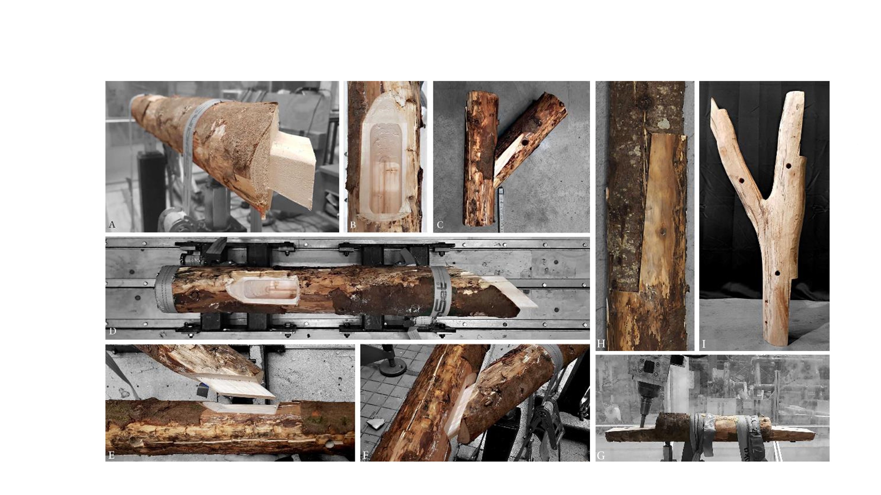
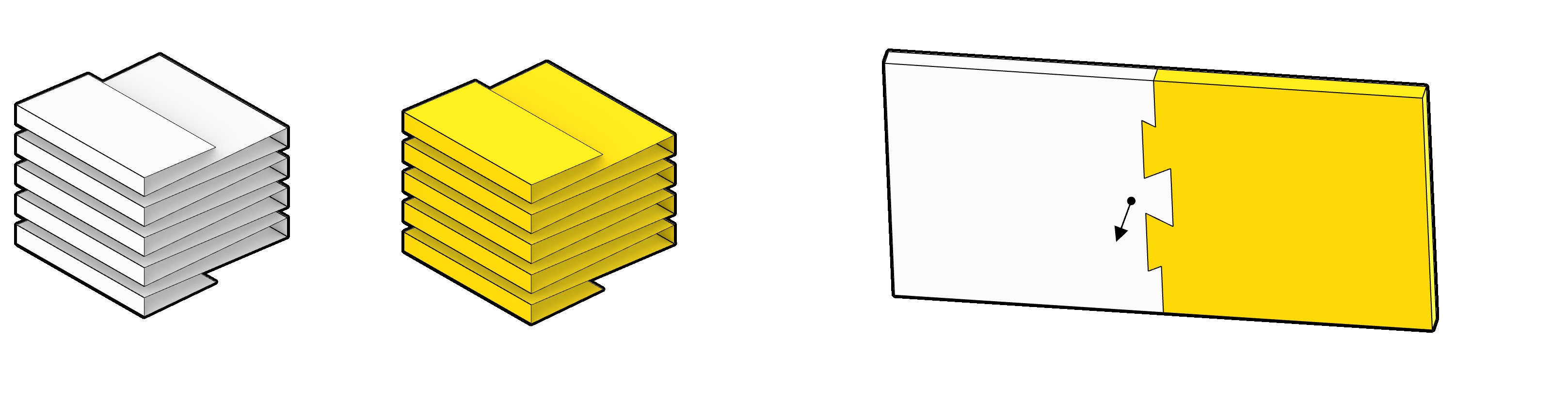
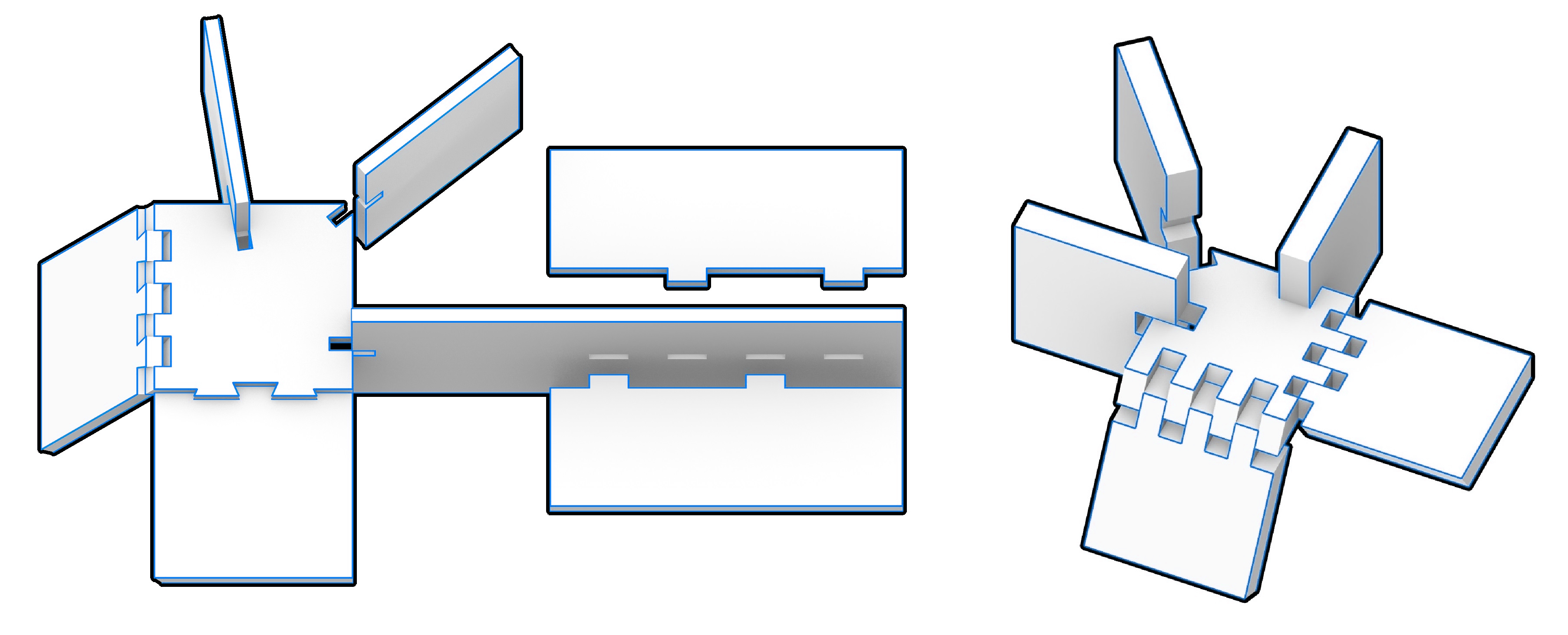
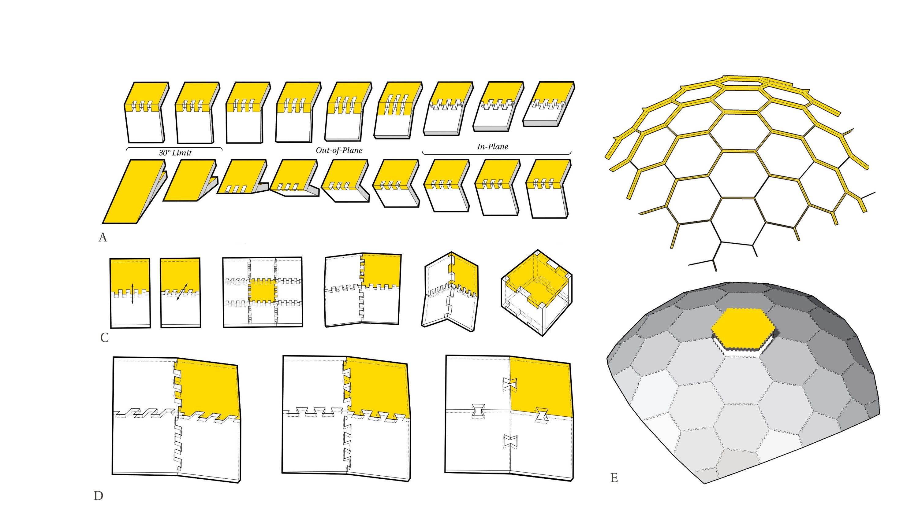
Joint: ss_e_op_1 Nejiri Arigata
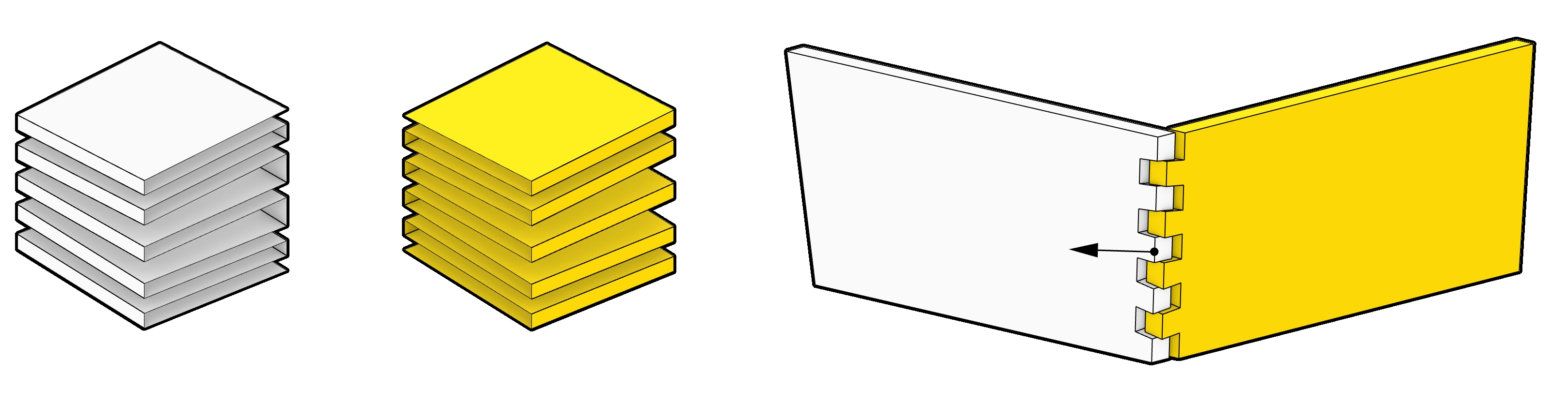
Joint: ss_e_op_2 Dovetail
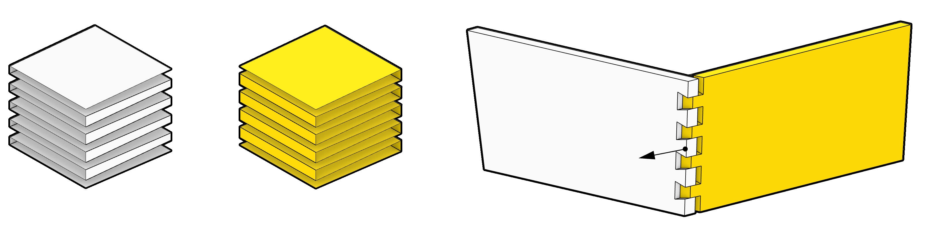
Joint: ss_e_ip_0 Dovetail
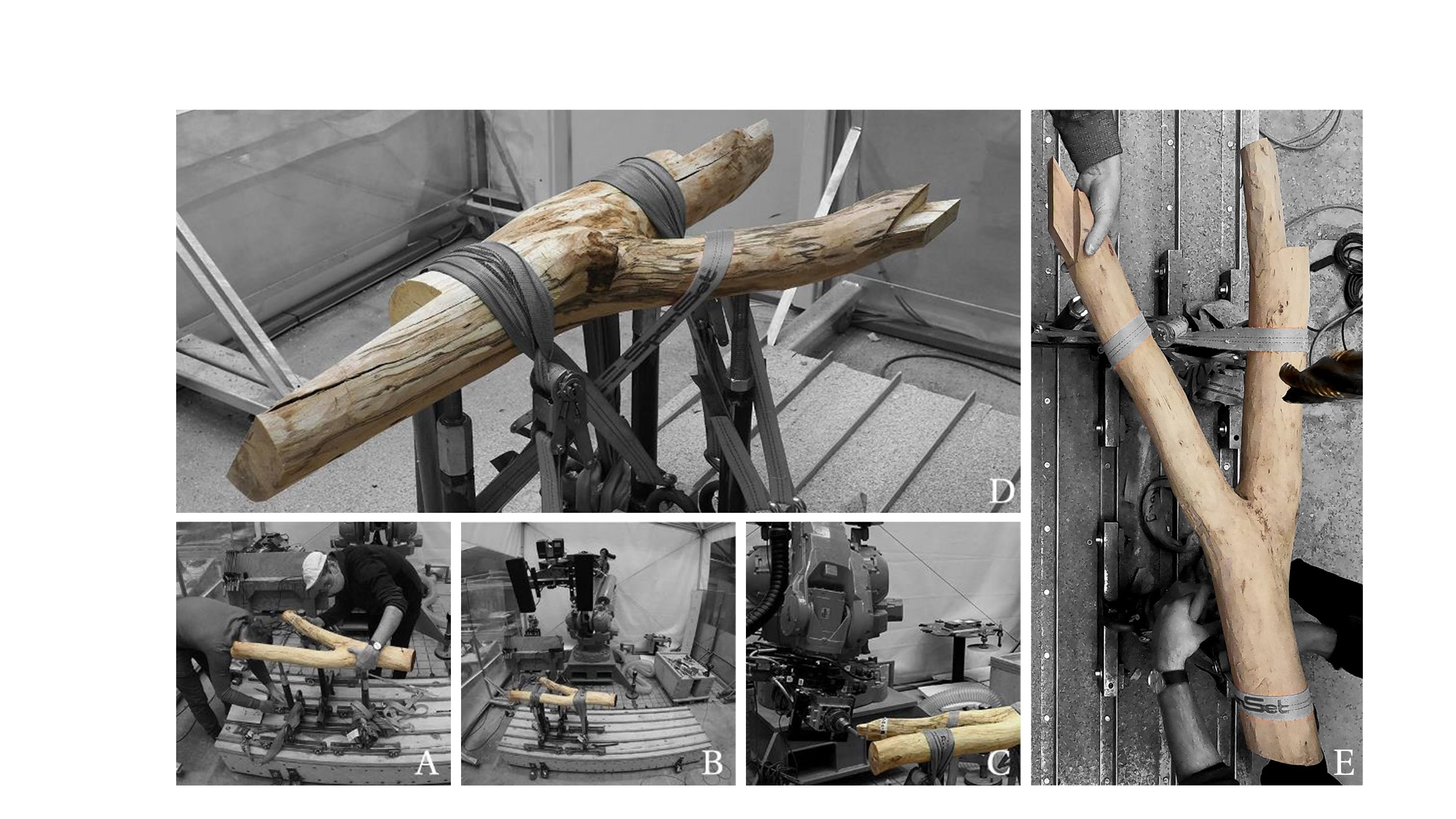
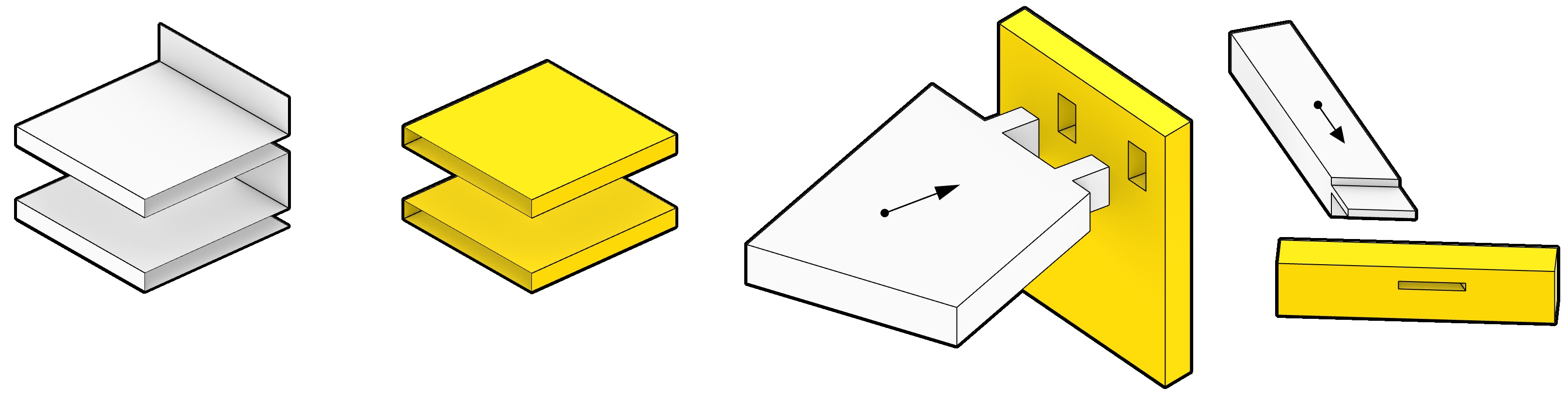
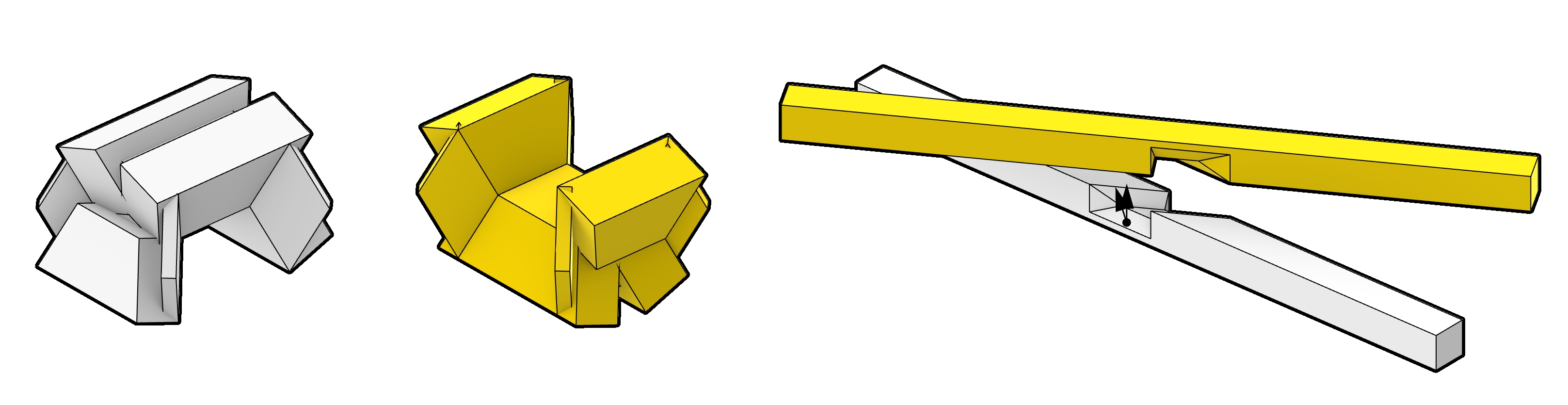
Joint: tenon mortise ts_e_p_2 (ts_e_p_0 - original) (start and end point of the joint line are skipped)
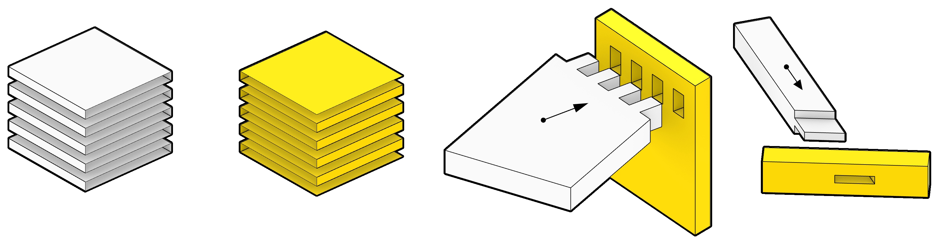
Joint: Annen joint - ts_e_p_3 (ts_e_p_2 - original)
Joint: cr_c_ip_0 cross
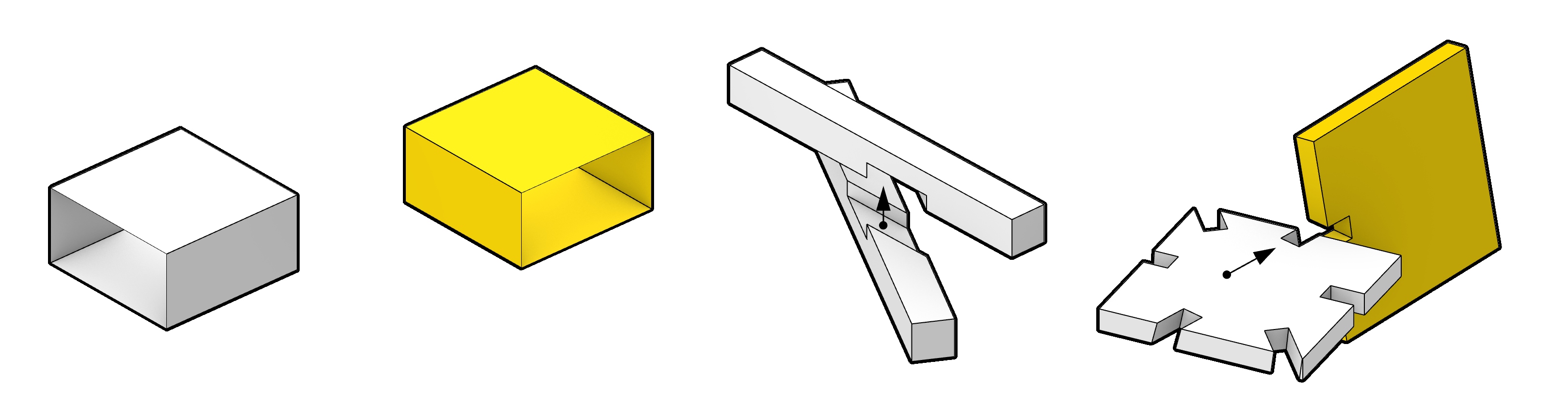
Joint: cr_c_ip_1 conic cross
- To-do joints types:
snap-fit joint
keys
tenon-mortise beams
tenon-mortise half beam
scarf
screws
- To-do others:
flipping case
BLT
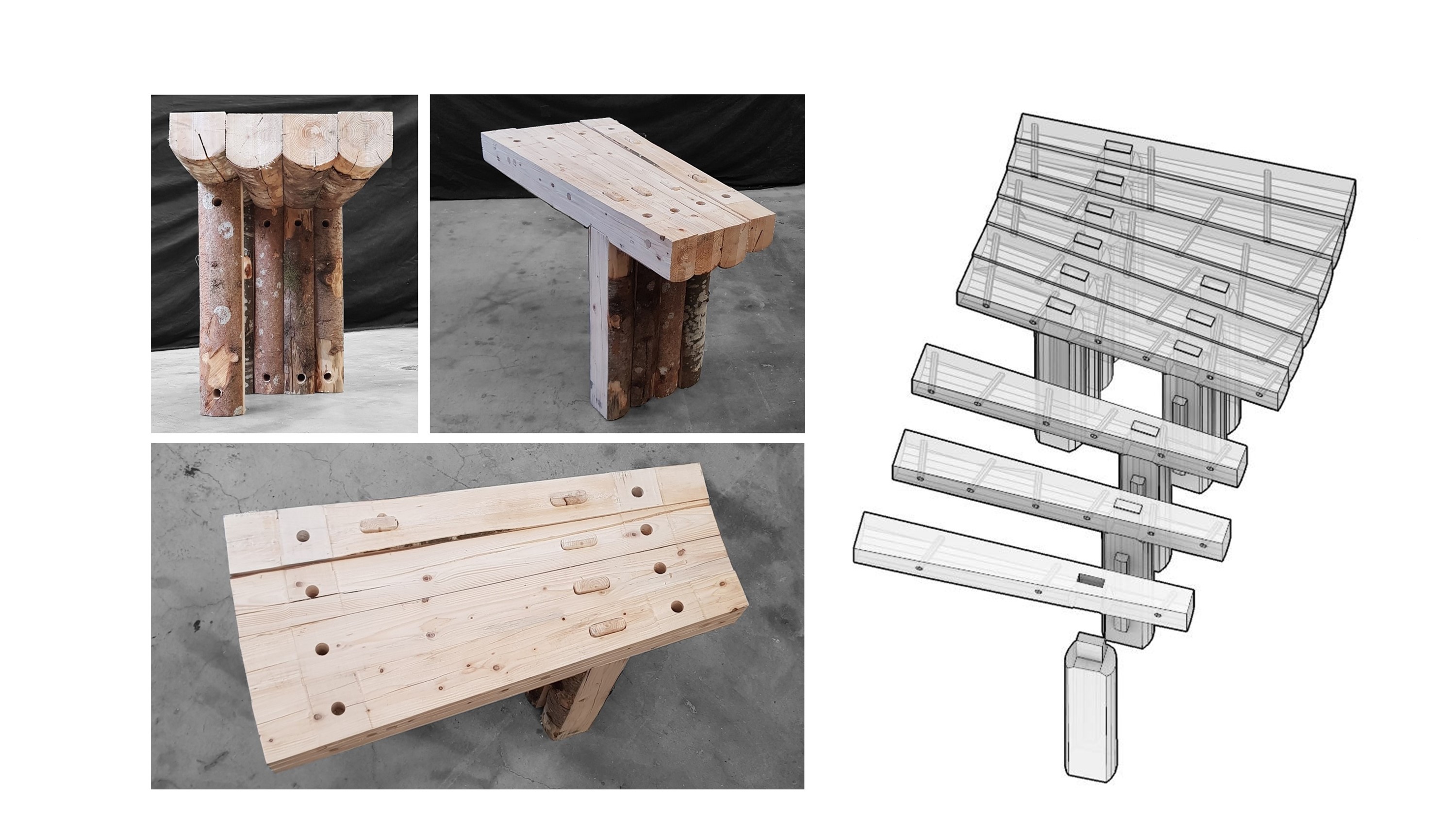
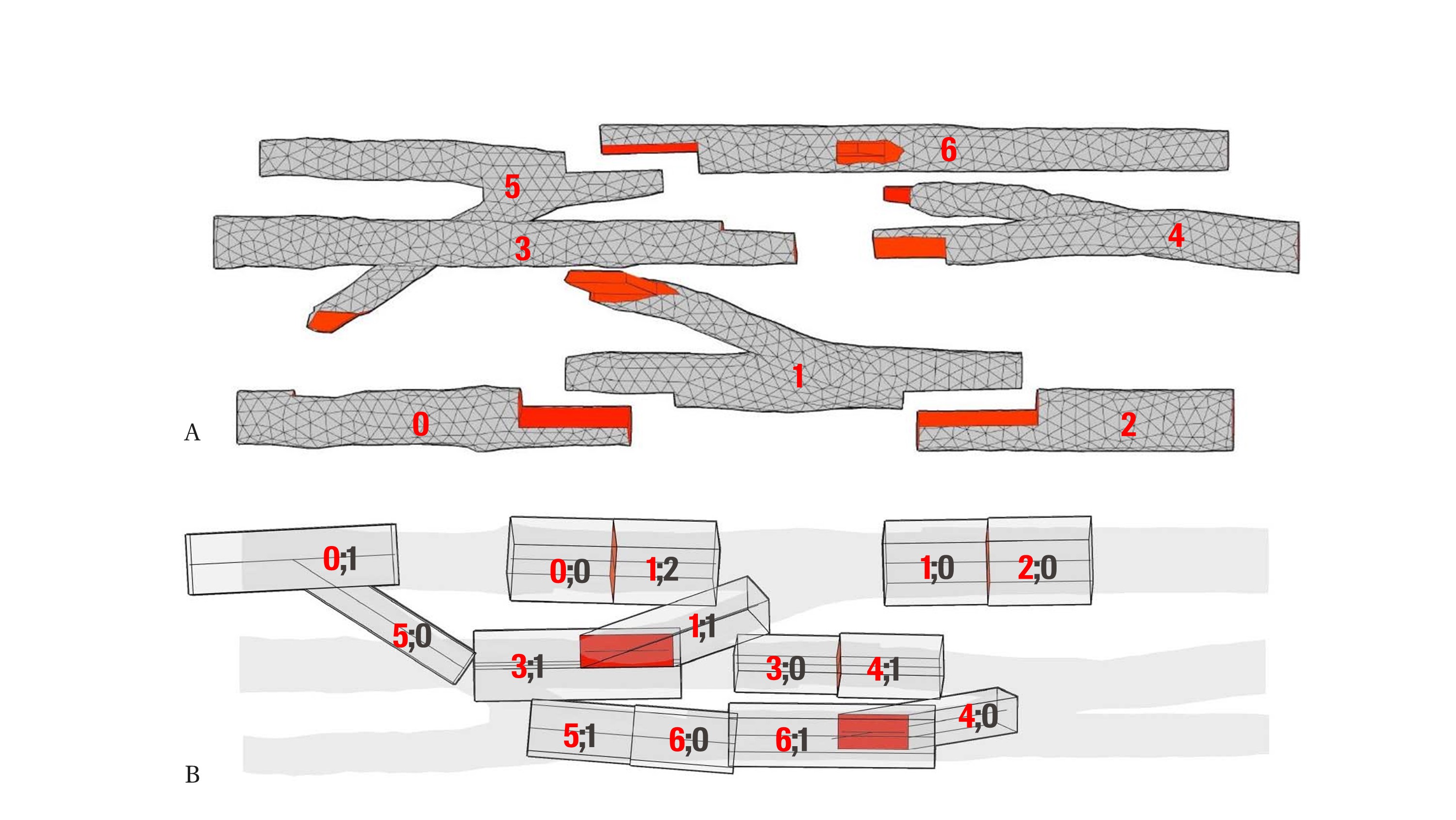
Element
- Code Implementation:
Element is specified as a pair of polylines, with planes for each side, in a beam case it is only a central polylines
j_mf property track joints (joint id, male/female, parameter on edge)
mesh boolean: a) reference shapes, b) joints polygon pairs
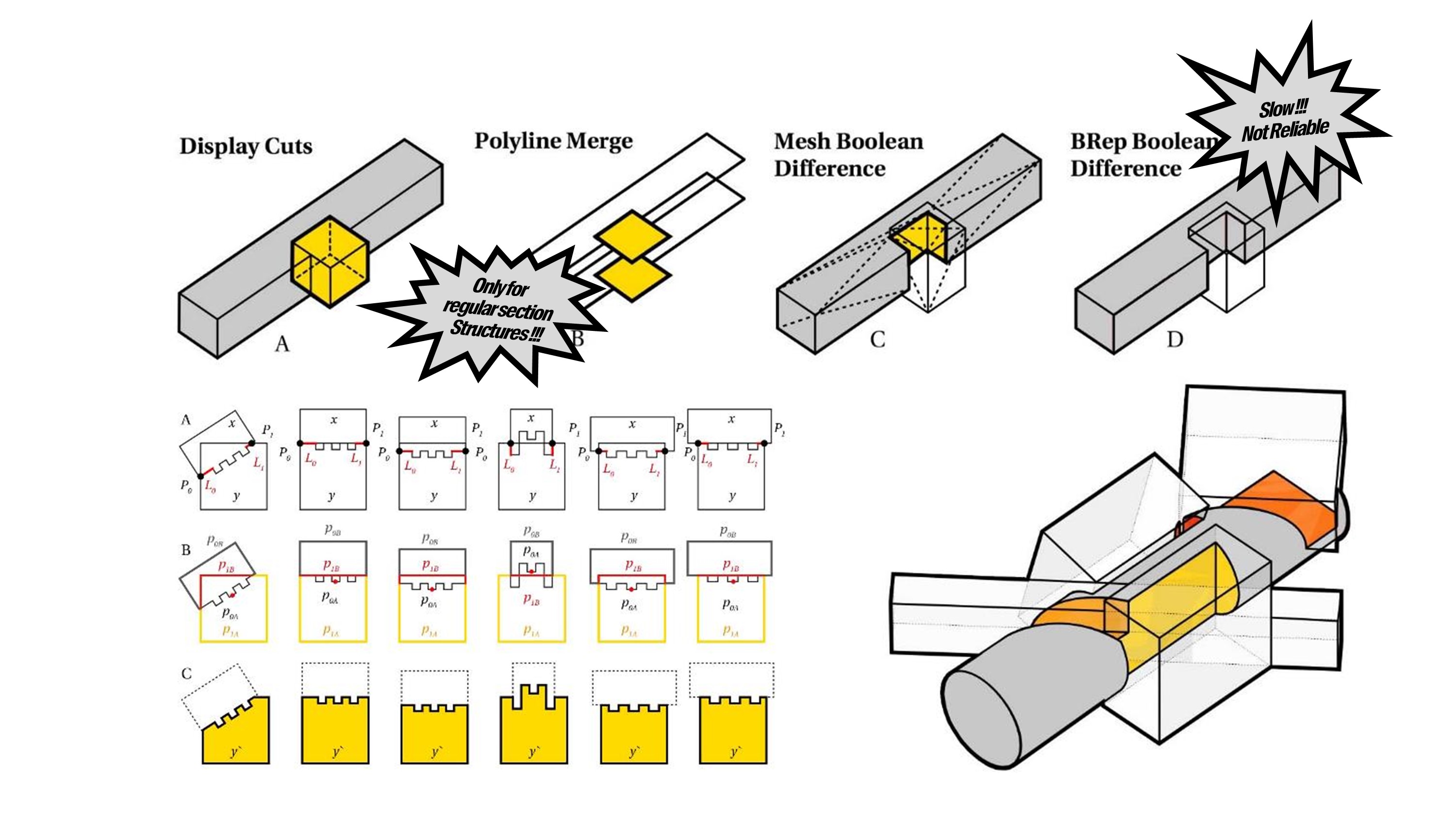
- Merge:
plate geometry can be merged, for beams boolean difference must be performed
Insert face joints inside edge
Insert between multiple edges (open polylines + closed polygons)
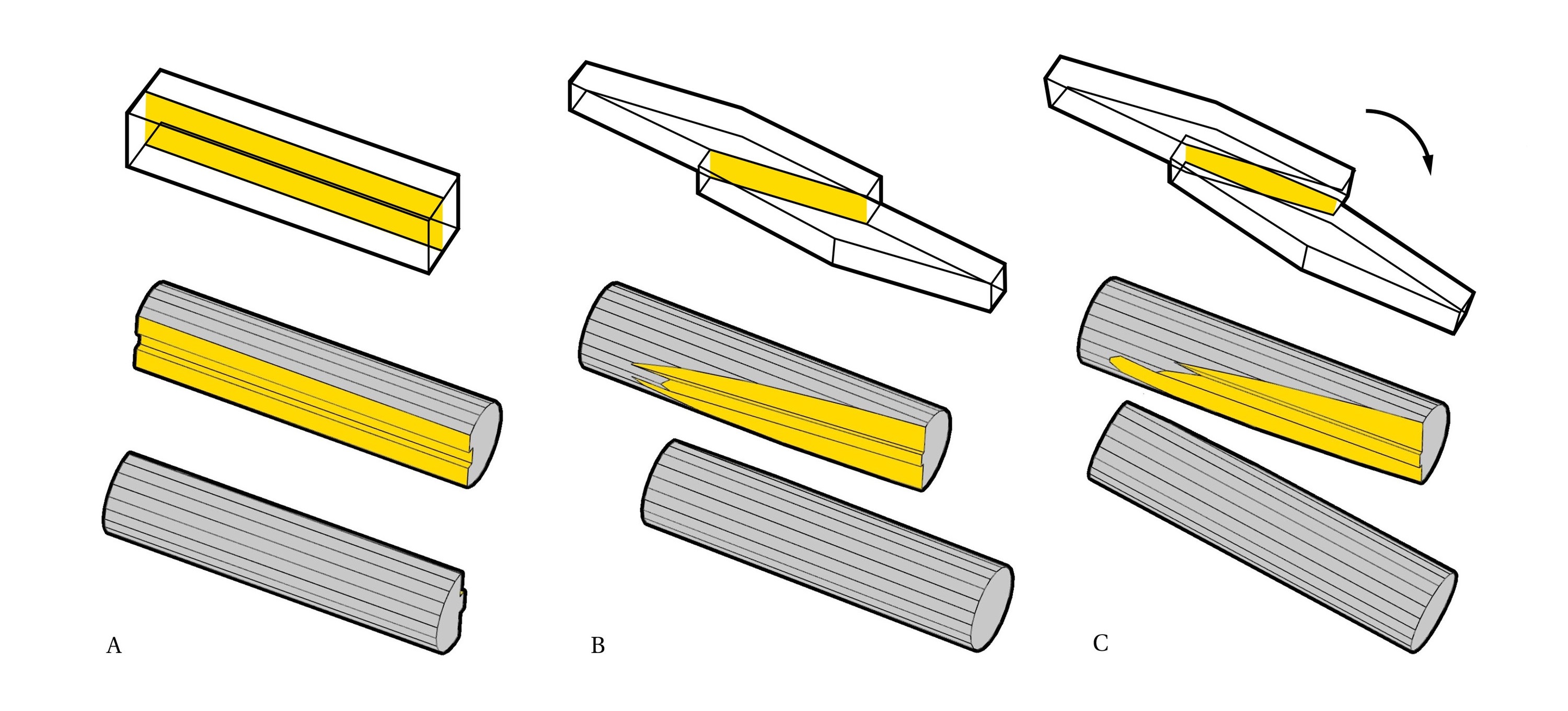
Cut projection and insert in polygon (case when side-side joints are rotated e.g. butterfly)
Mesh boolean: a) reference shapes, b) joints polygon pairs
- Grouping:
Introduce unordered_map to track grouping like sorted lists x;x;x
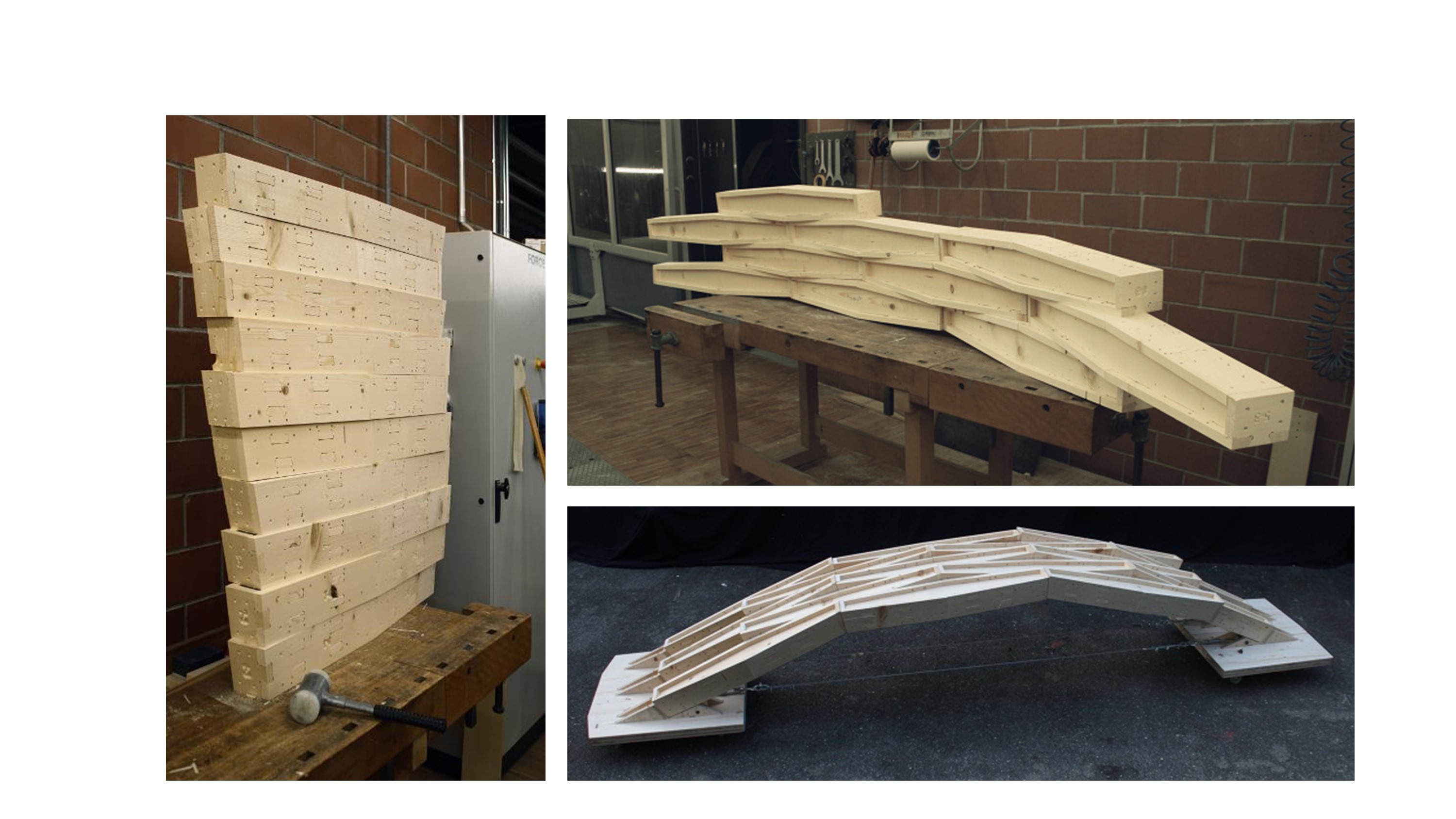
Presentation
Element is a List of Joints
Element Group
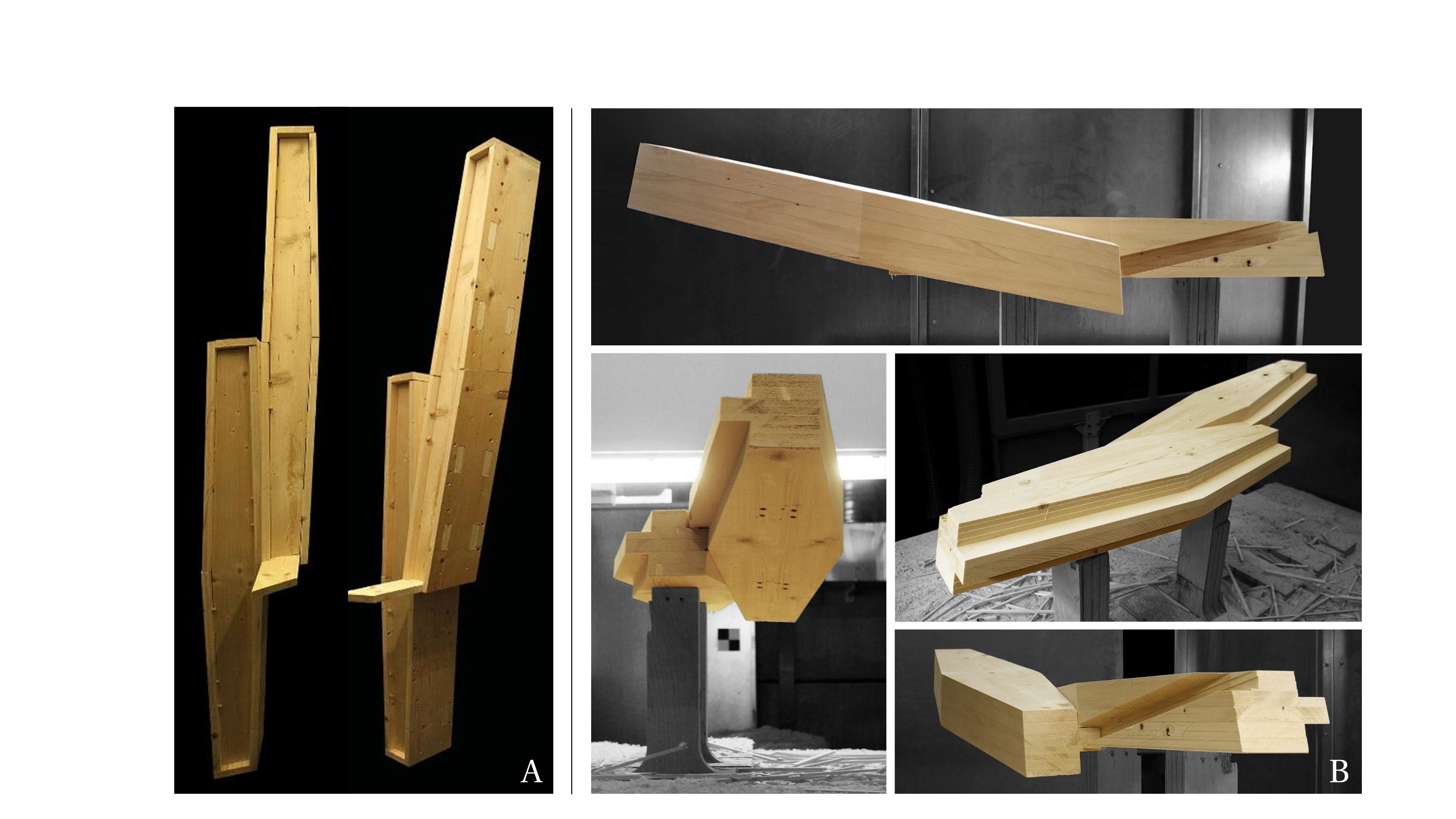
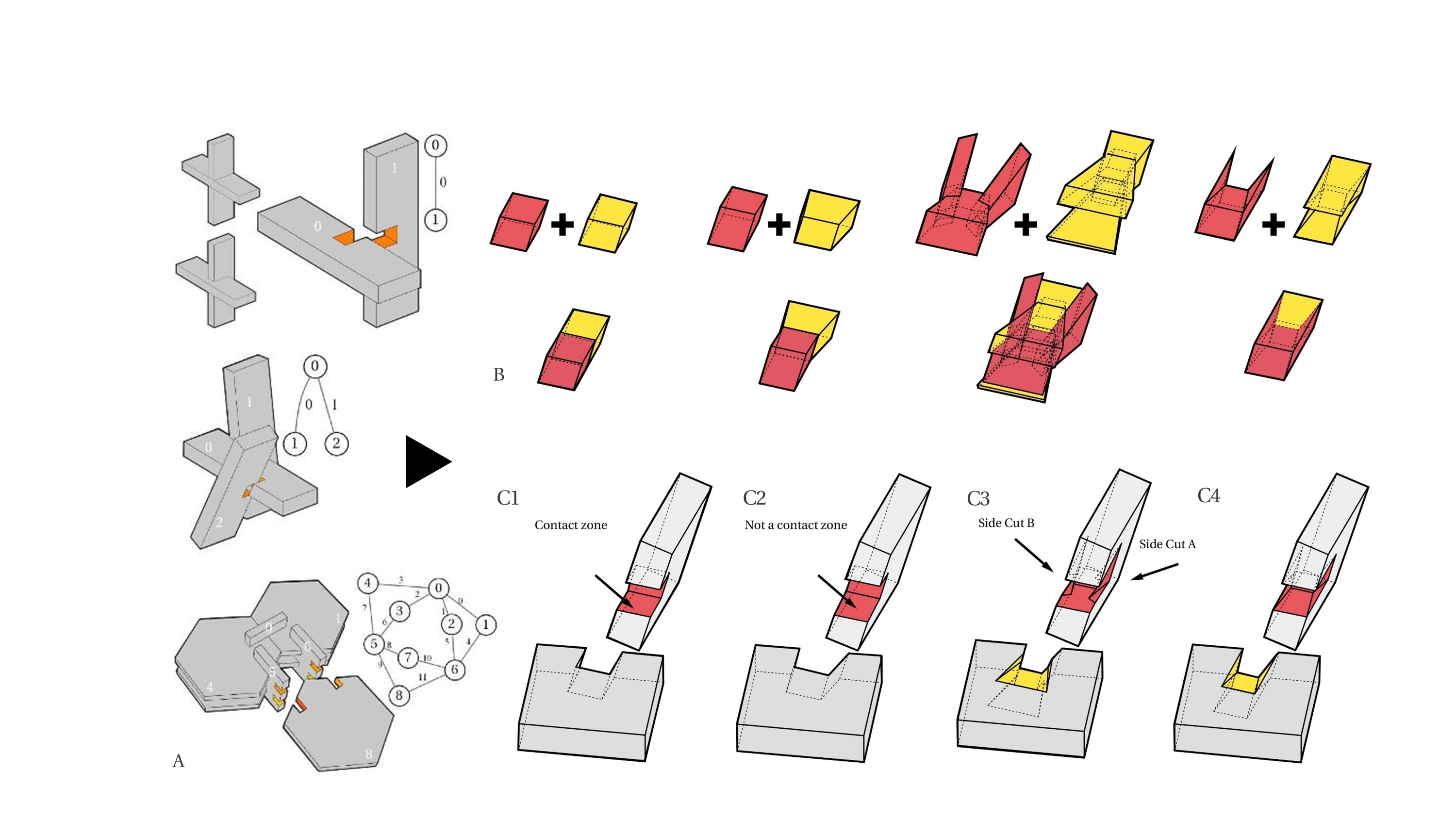
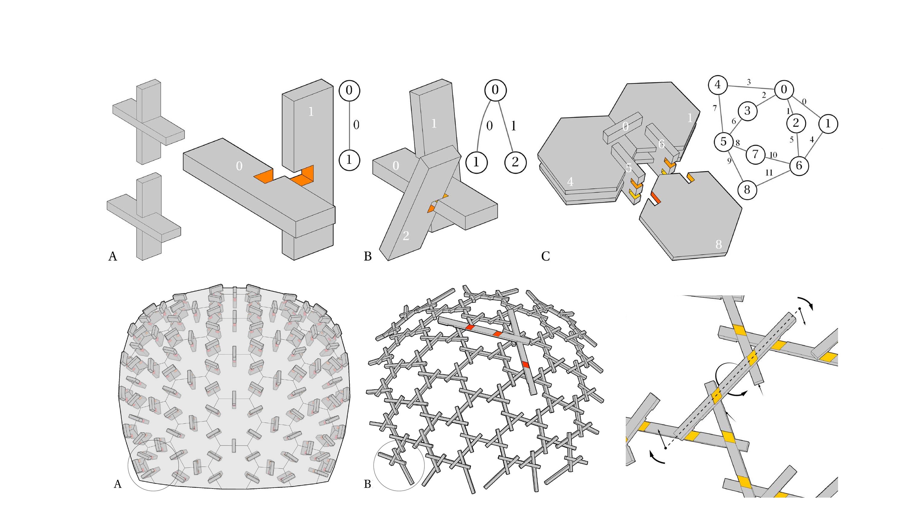
Joint - Tiles + Undirected-graph. Tile = Female + Male Cuts
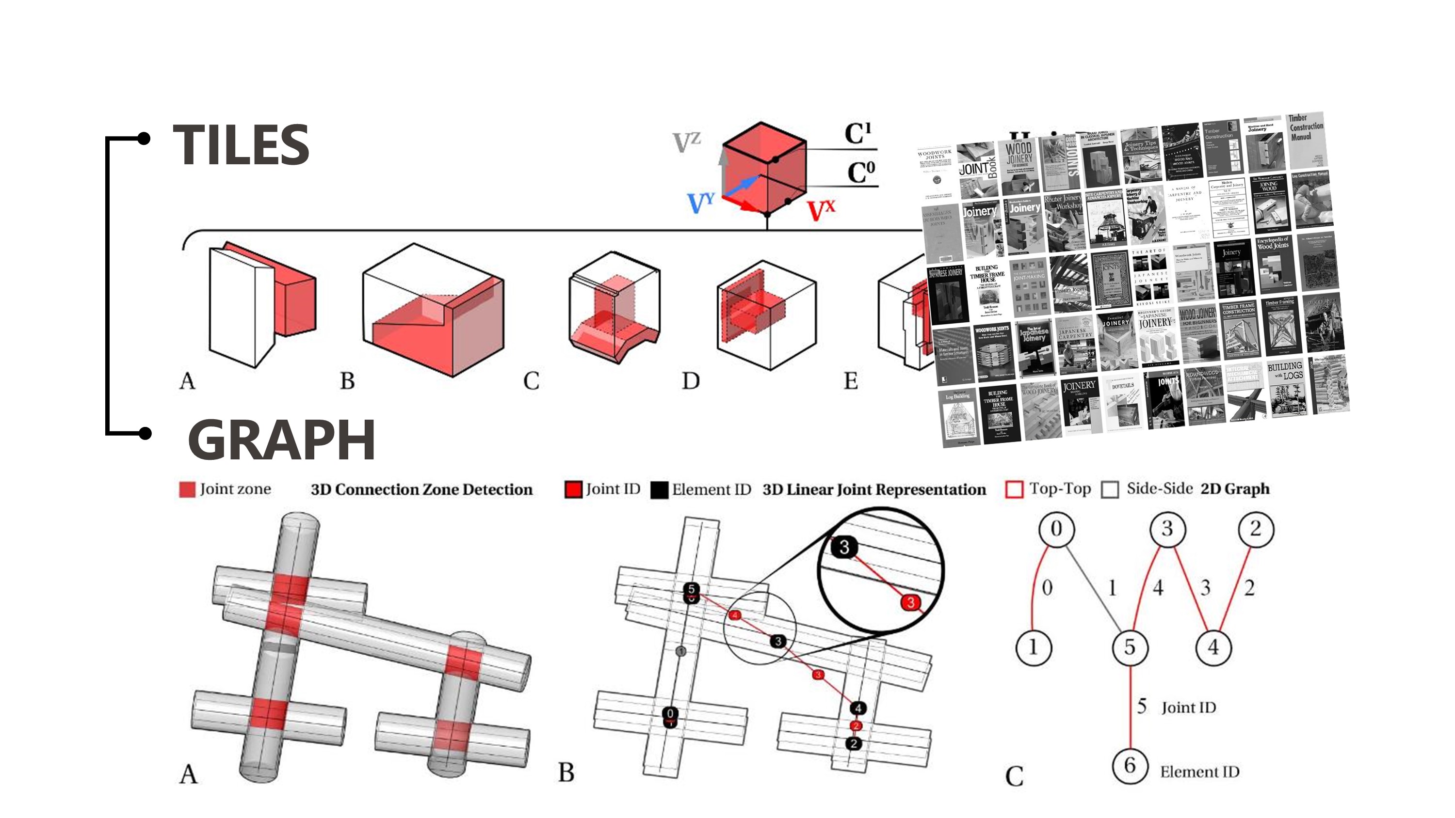
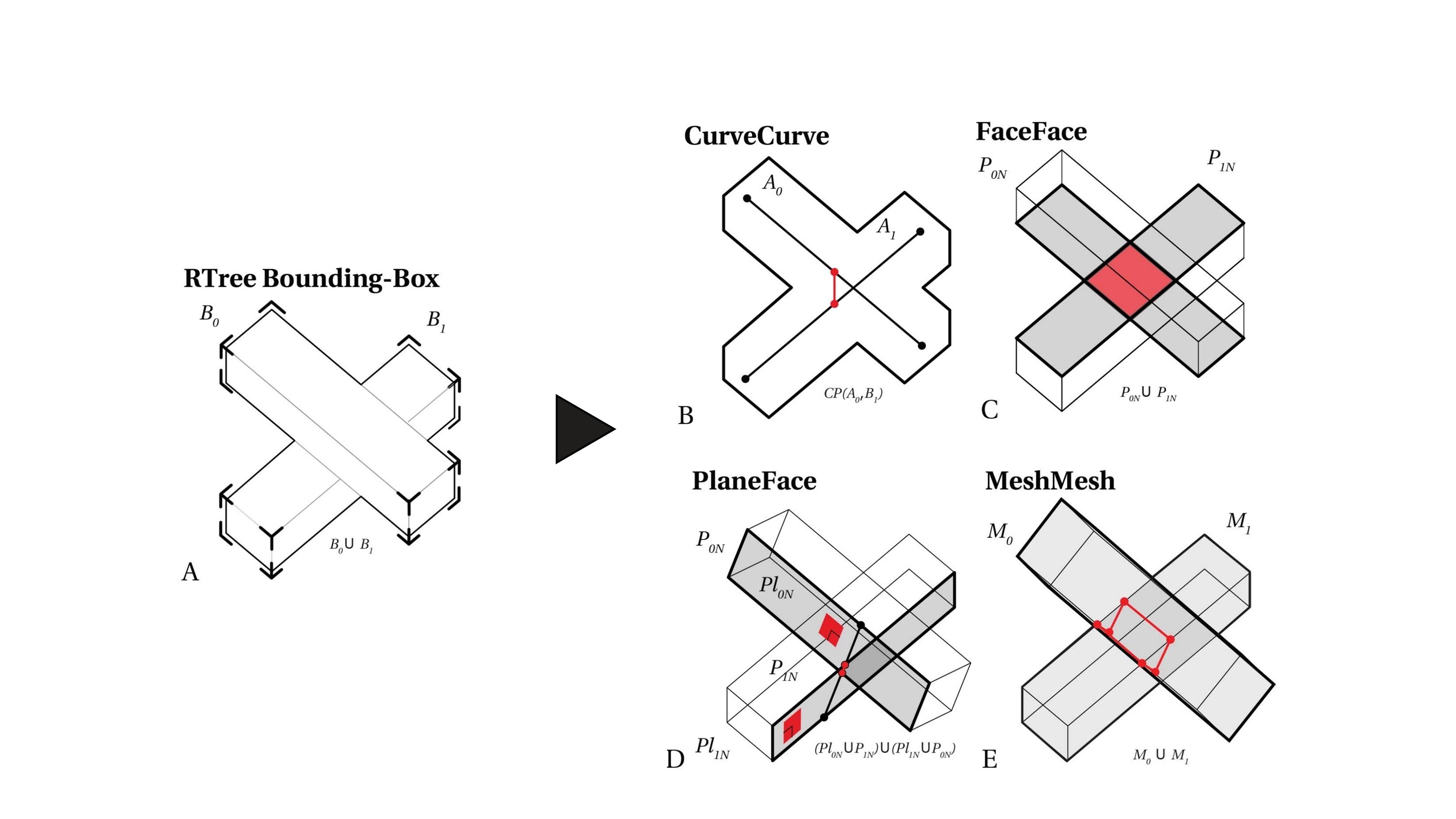
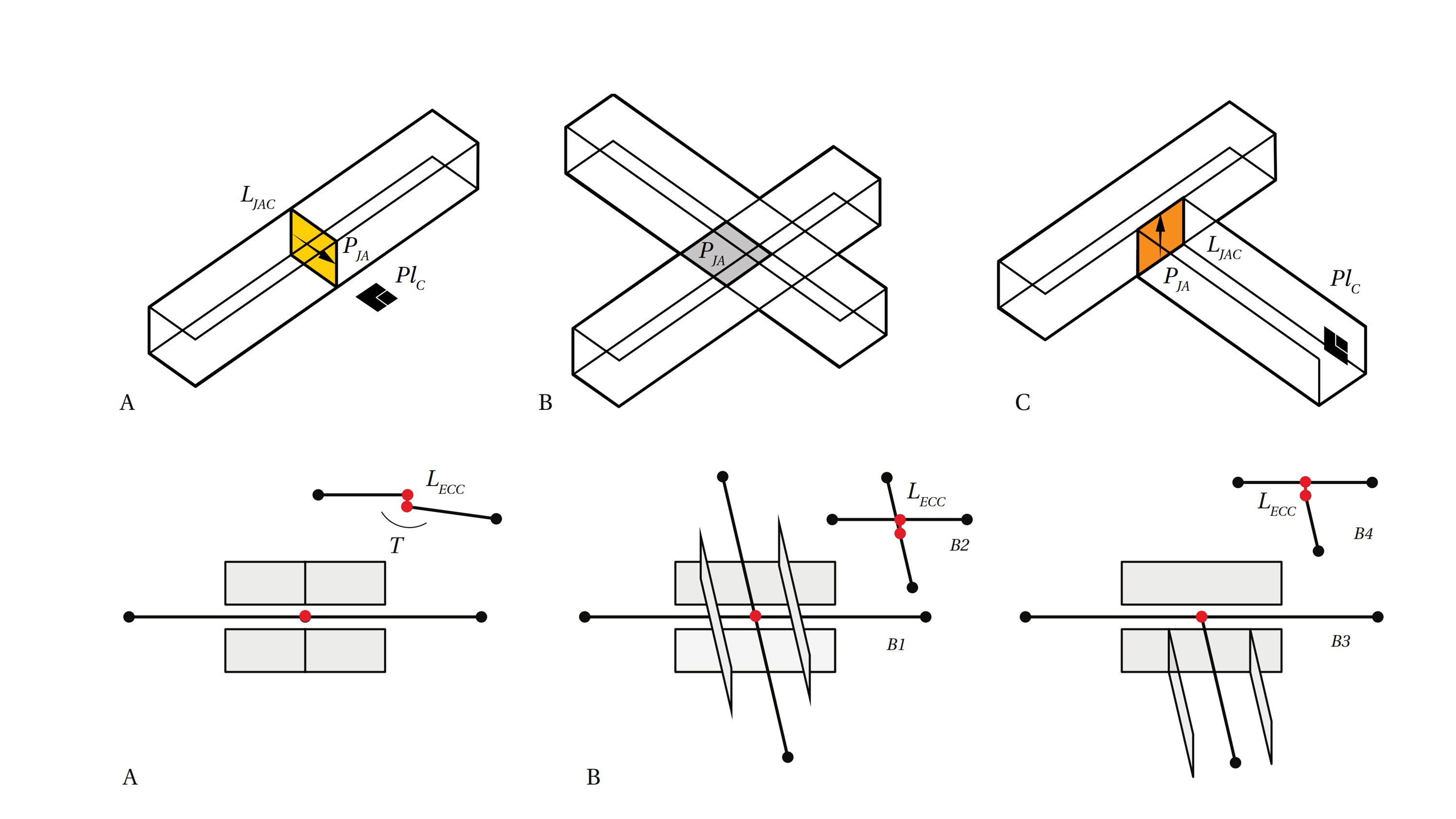
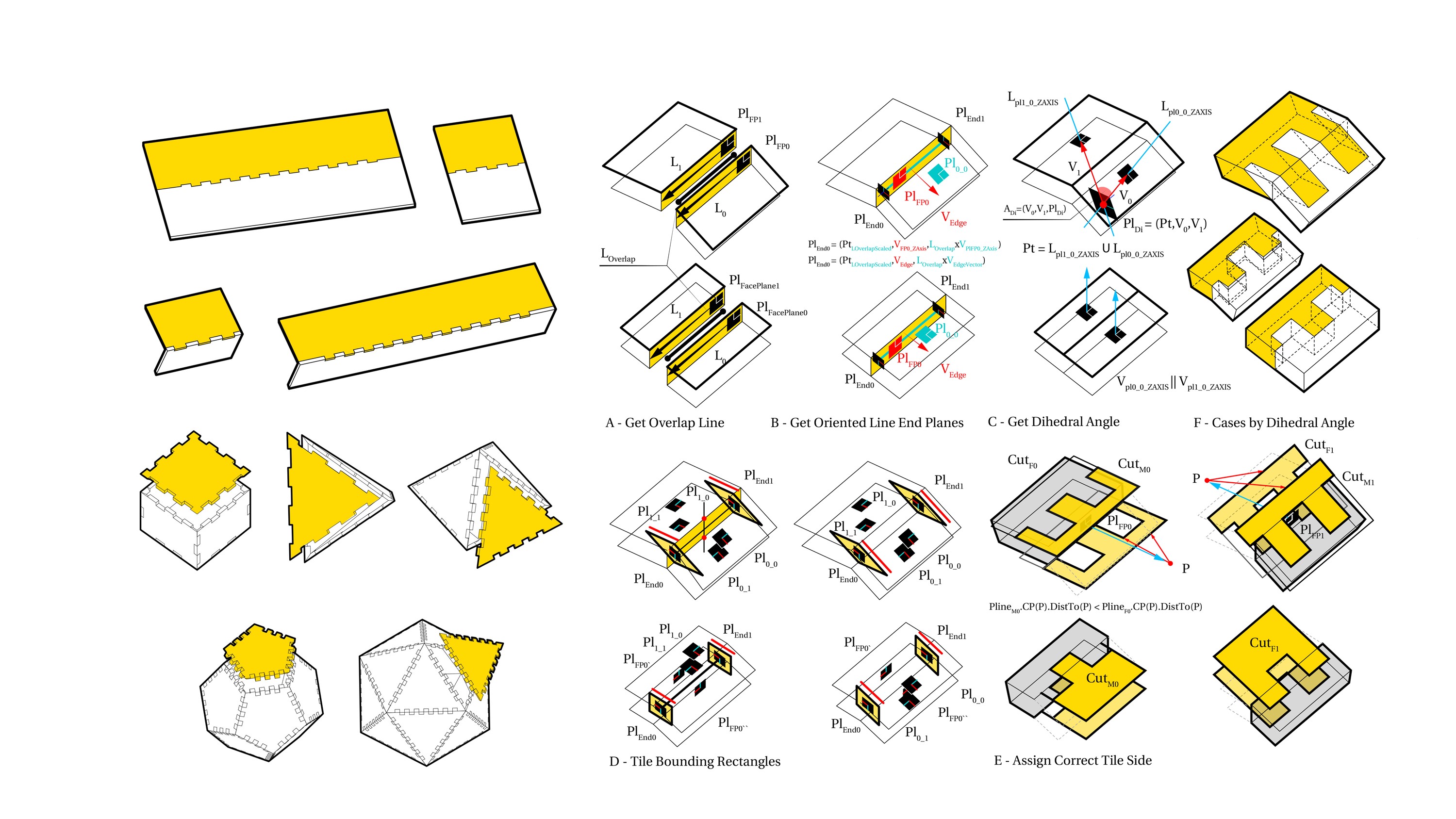
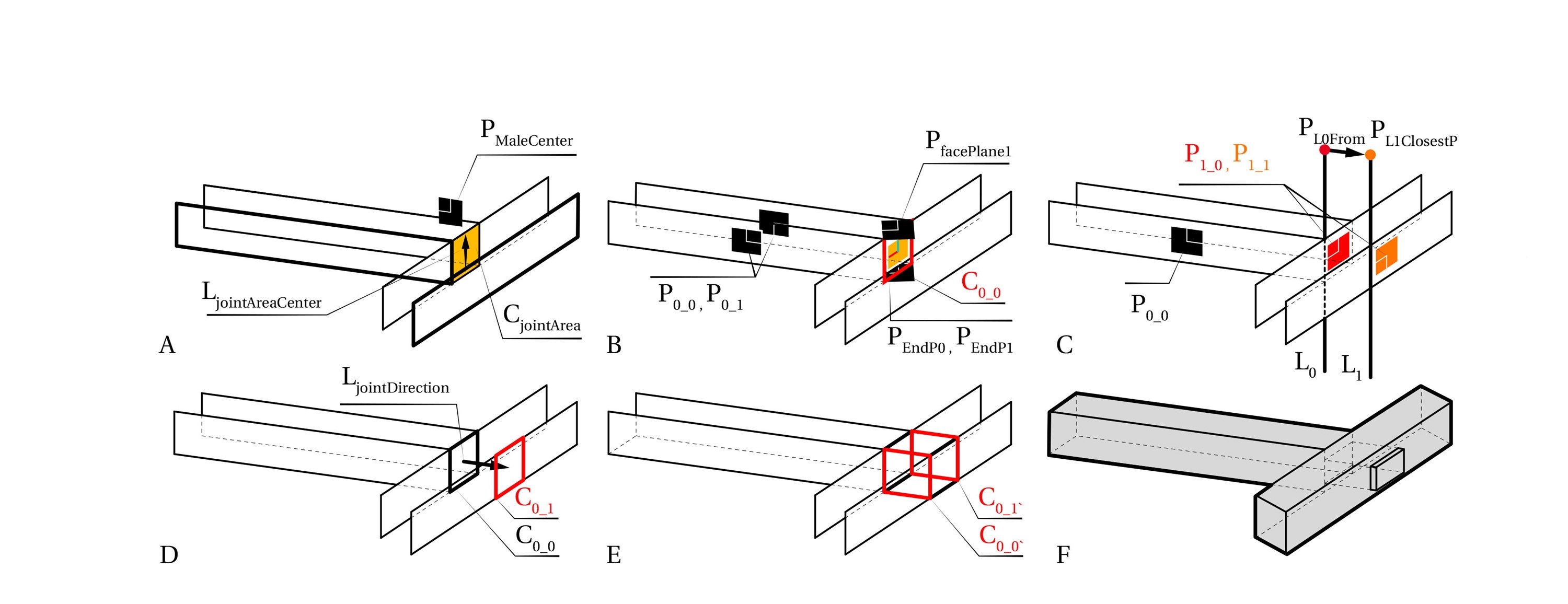
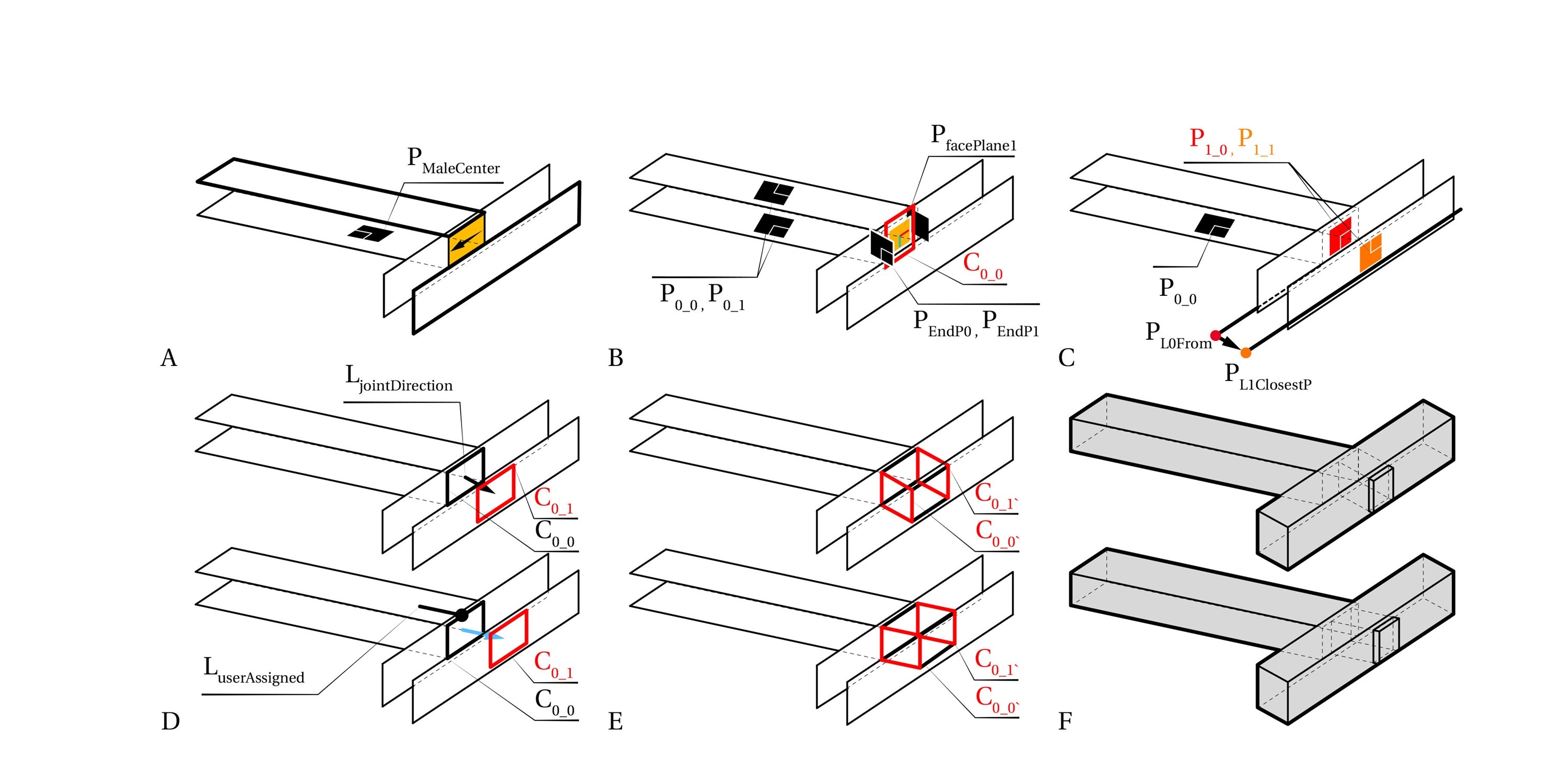
Search - Connection Detection
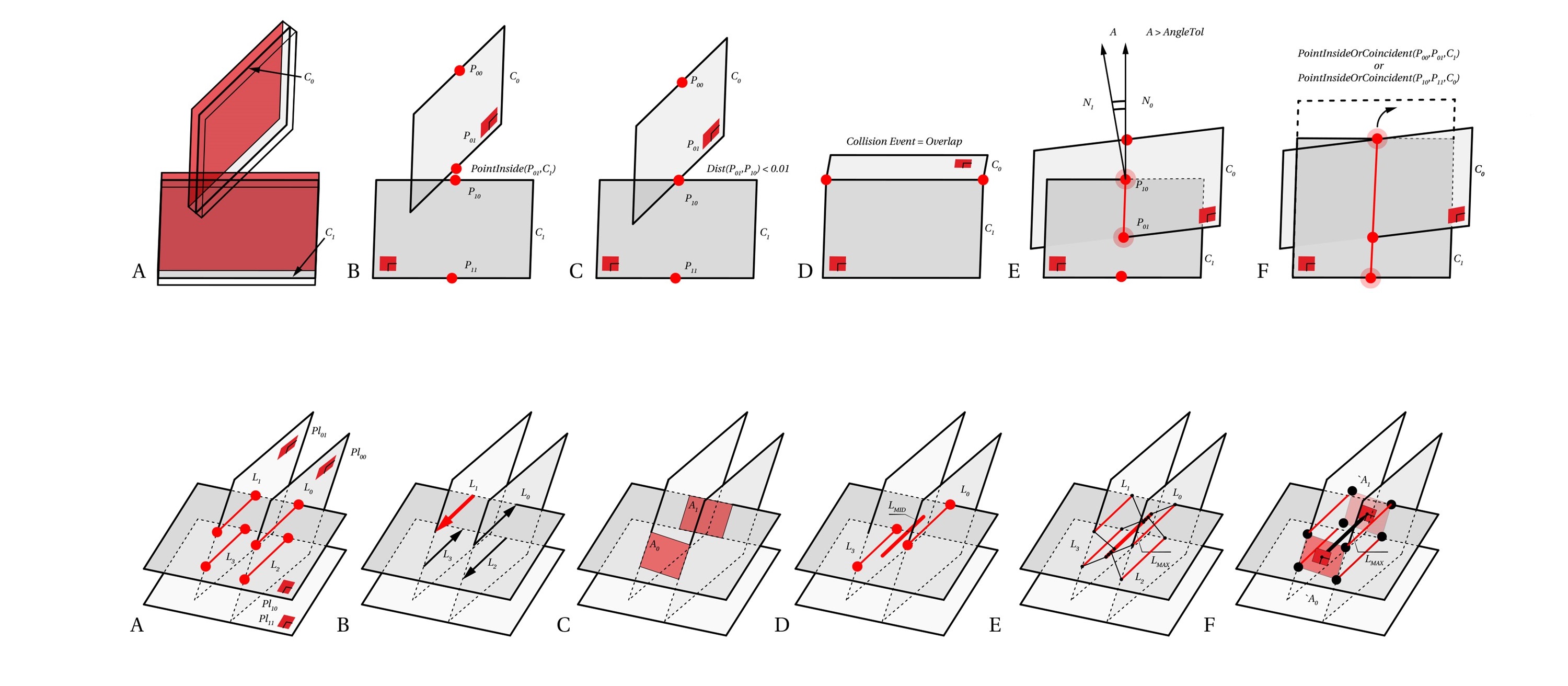
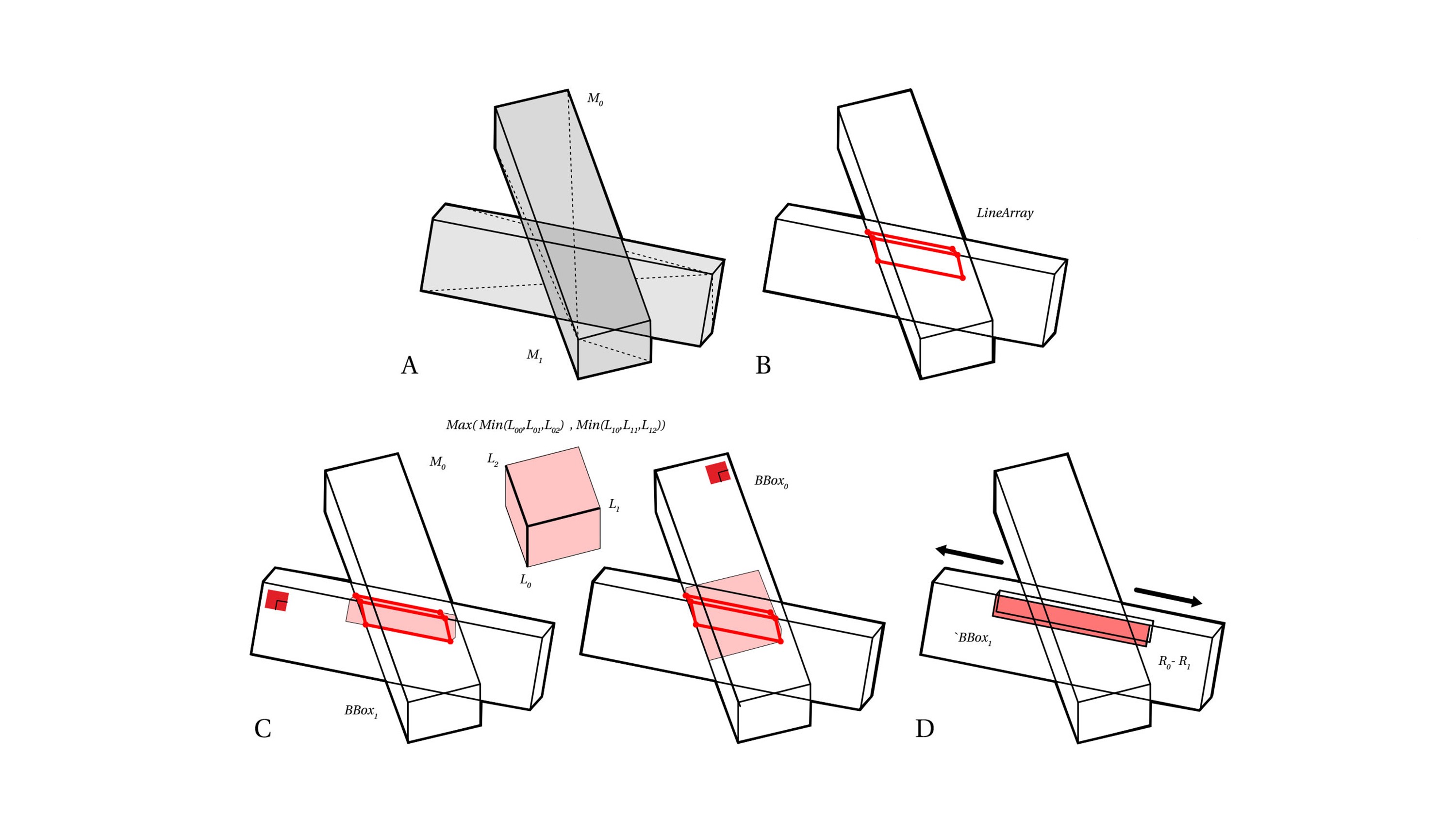
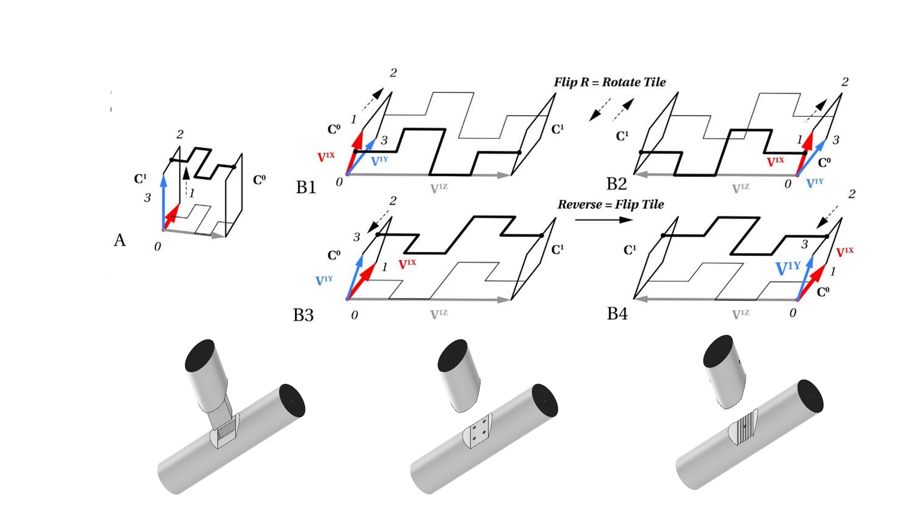
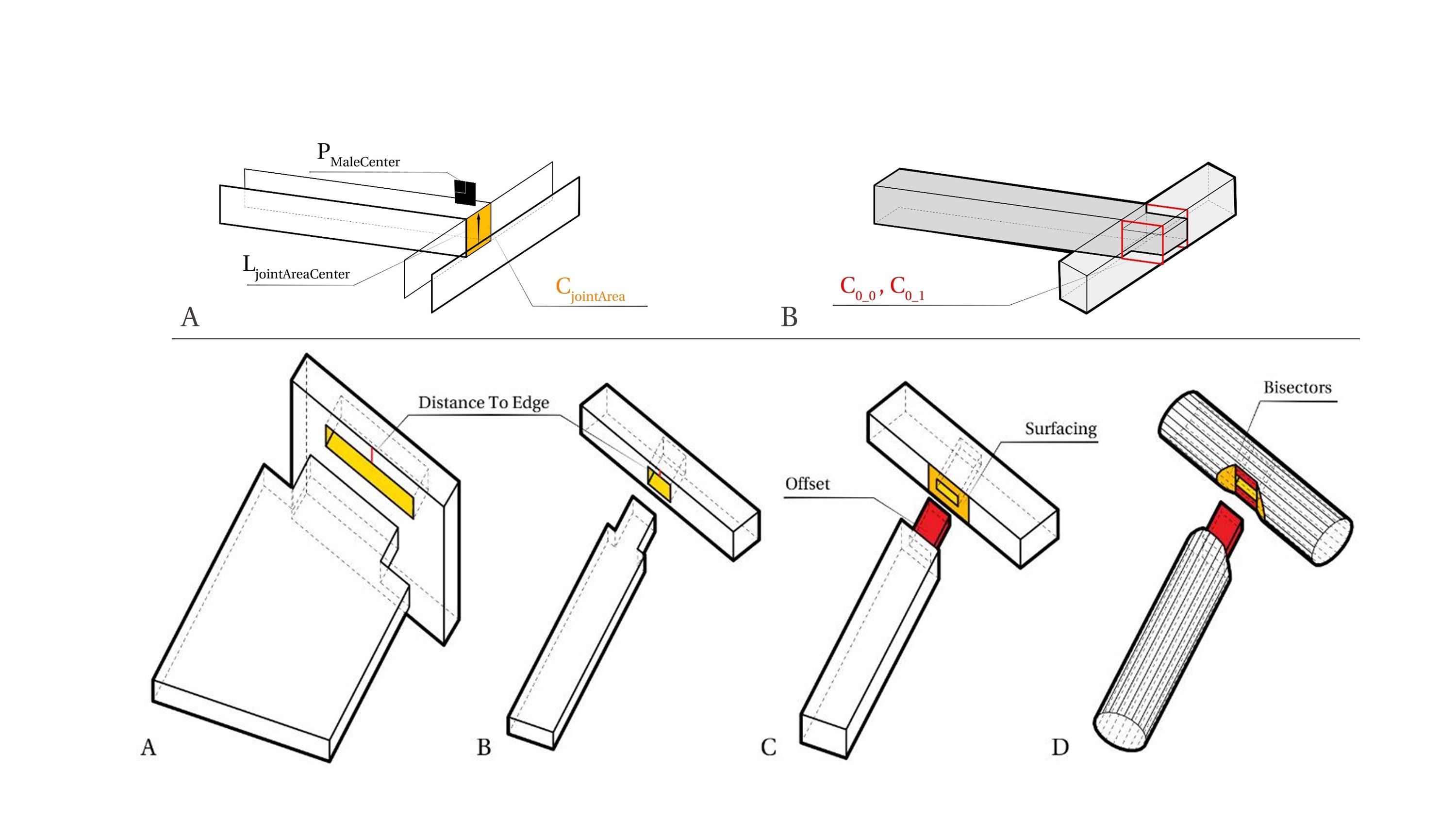
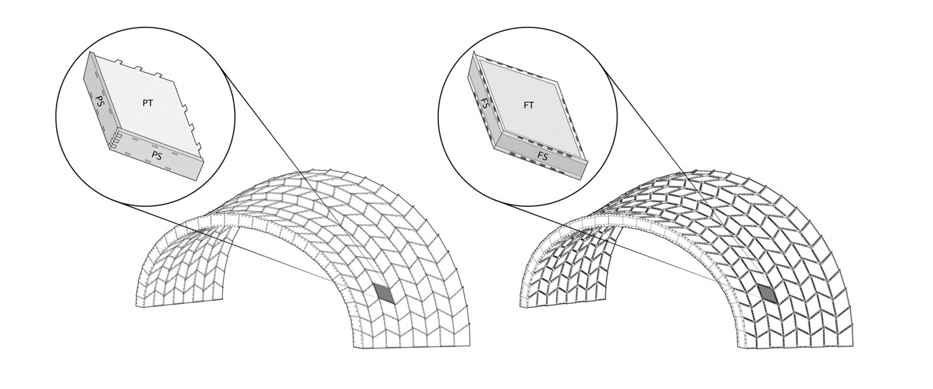
Tile - Change-of-basis Transformation
Boolean Methods for Digital Cuts
Side-to-side Topology
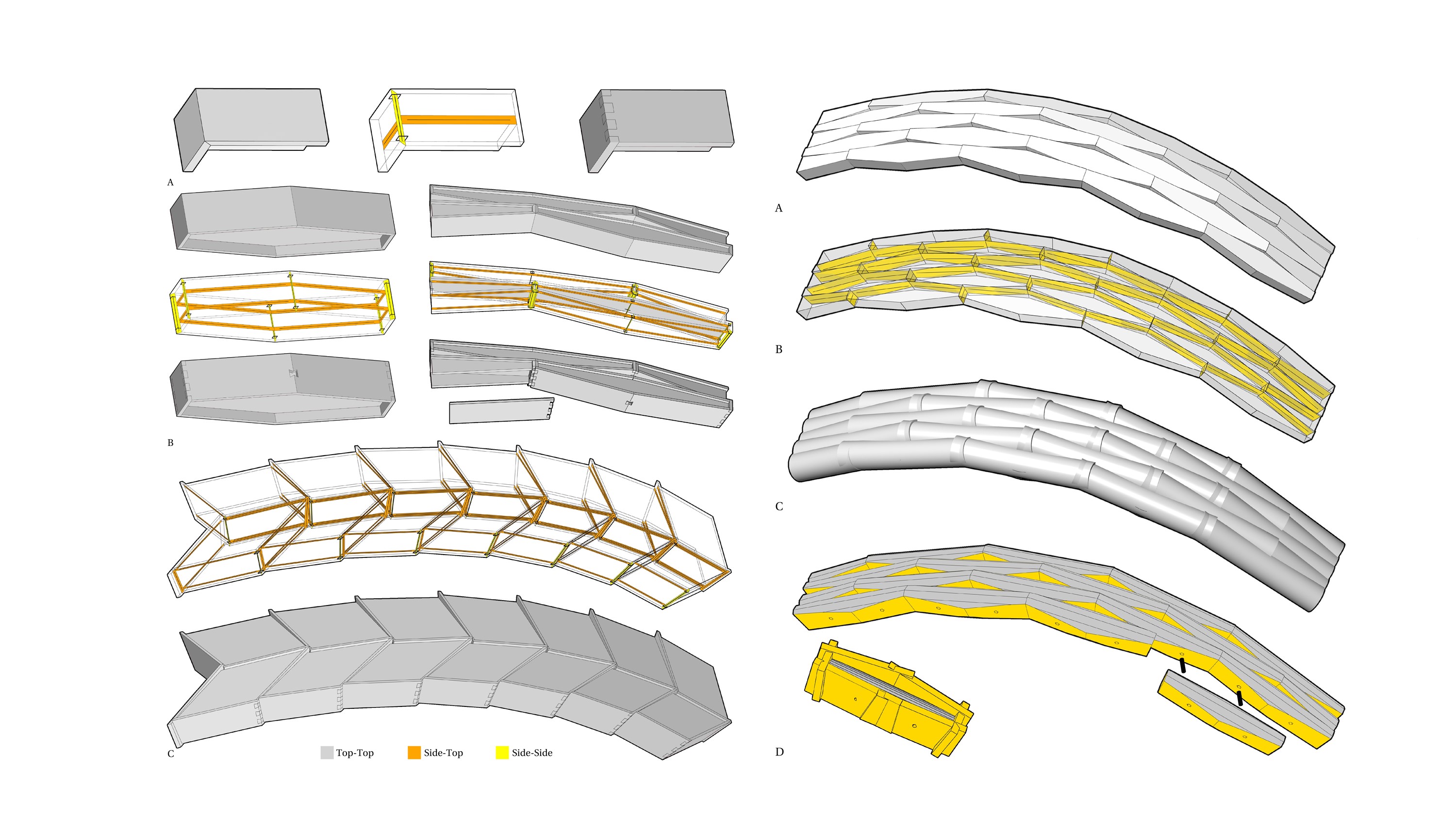
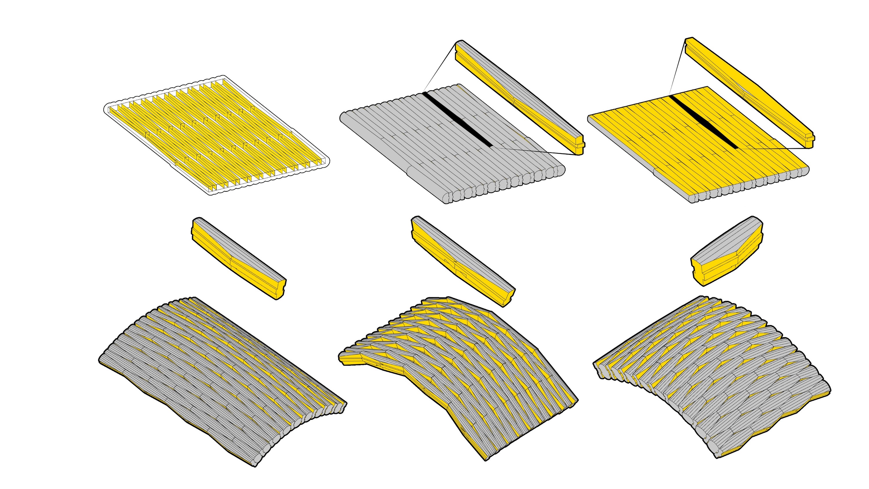
Side-to-top Topology
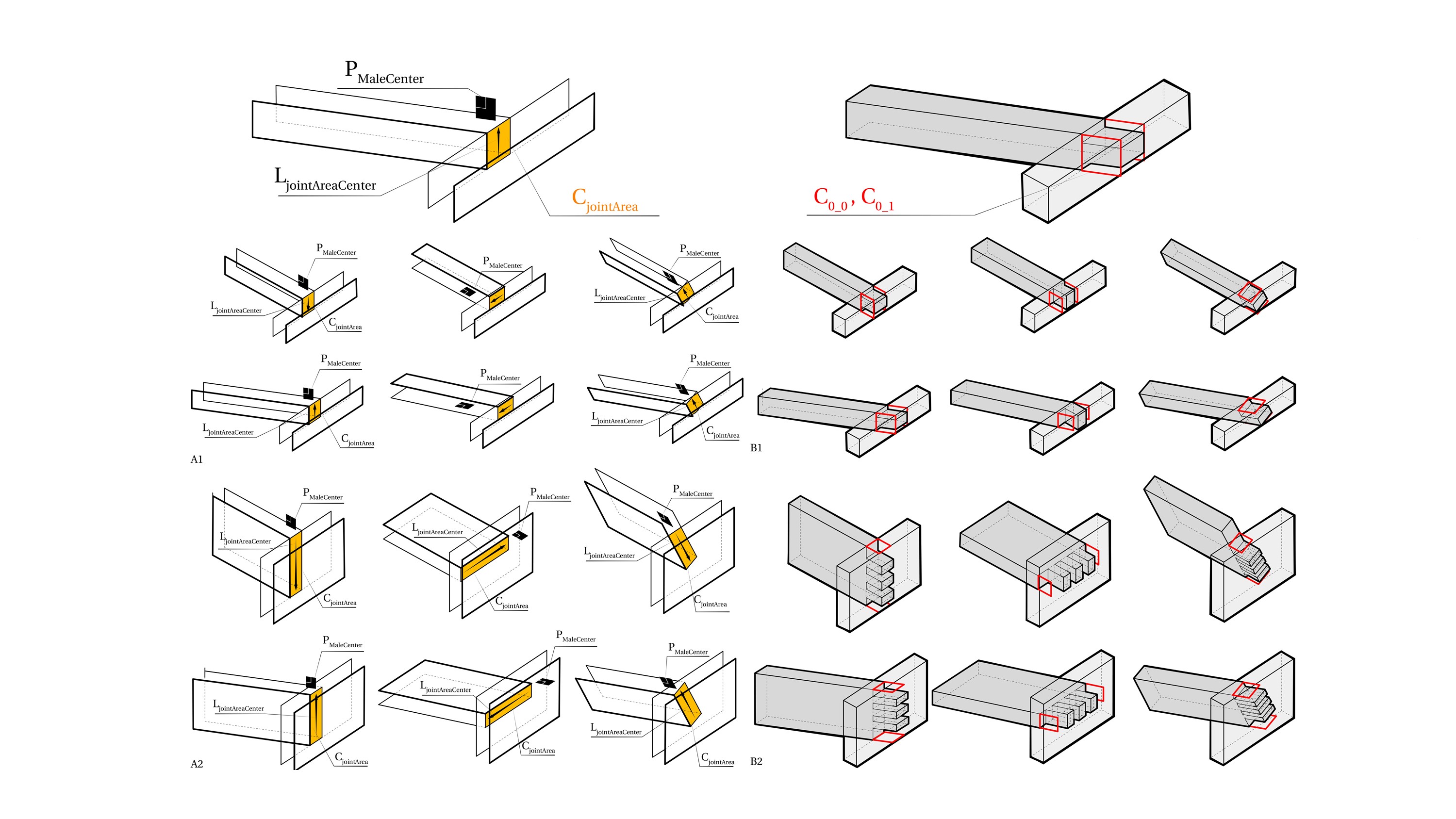
Cross Topology
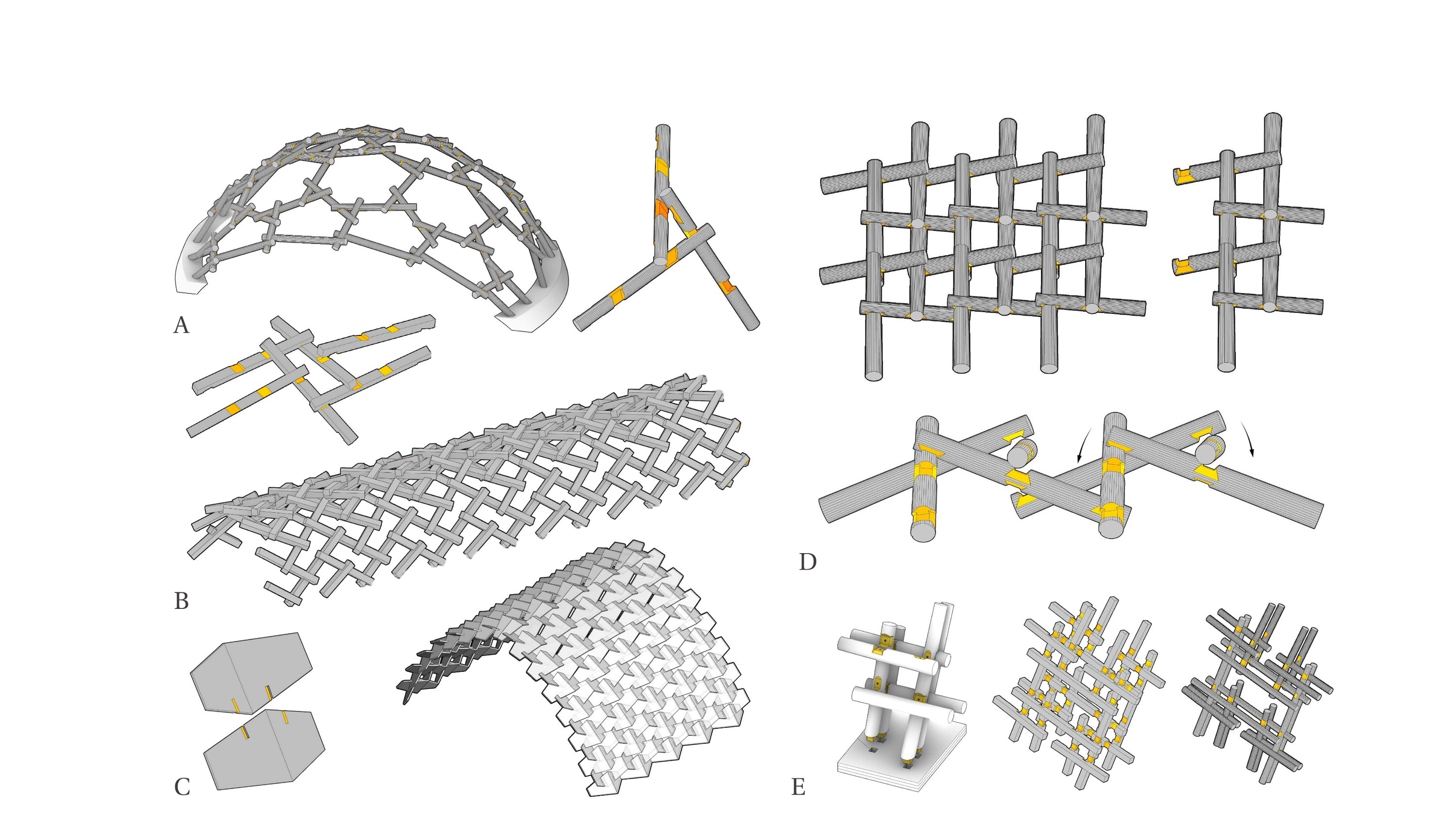
Mixed Topology